
Method and control system for a displacement device, with distance measurement in order to detect obstacles

a technology of displacement device and control system, which is applied in the direction of position/direction control, towing device, vehicle, etc., can solve the problems of short reaction time required for the control system, the input of braking signal and vehicle speed signal is not well suited to timely response to panic braking, and the corner of the semi-trailer is apt to strike against the cab. , to achieve the effect of minimizing fuel consumption, reducing the formation of vortex, and increasing the length

Inactive Publication Date: 2010-10-14
JOST WERKE
View PDF10 Cites 8 Cited by
  • Summary
  • Abstract
  • Description
  • Claims
  • Application Information

AI Technical Summary

Benefits of technology

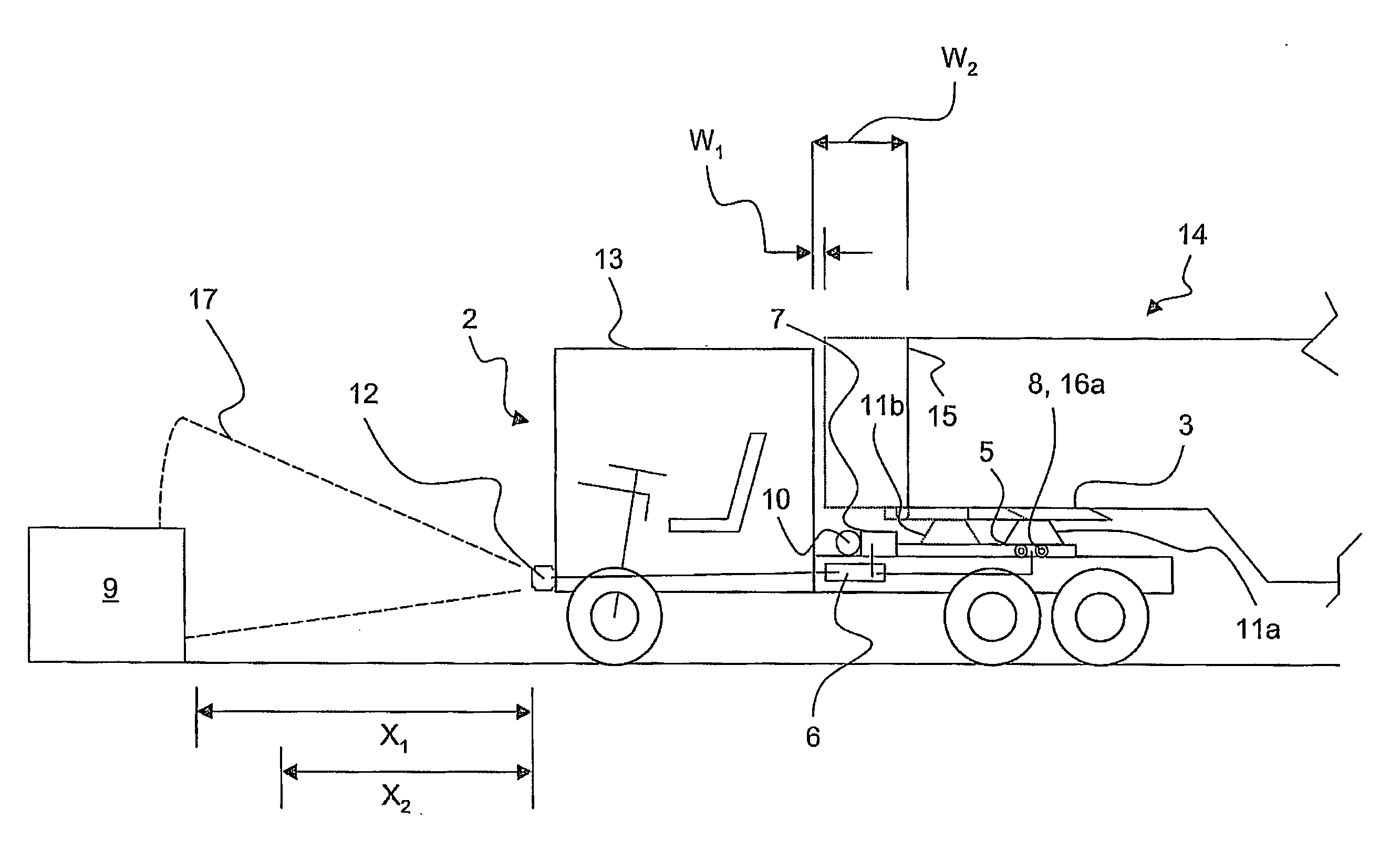
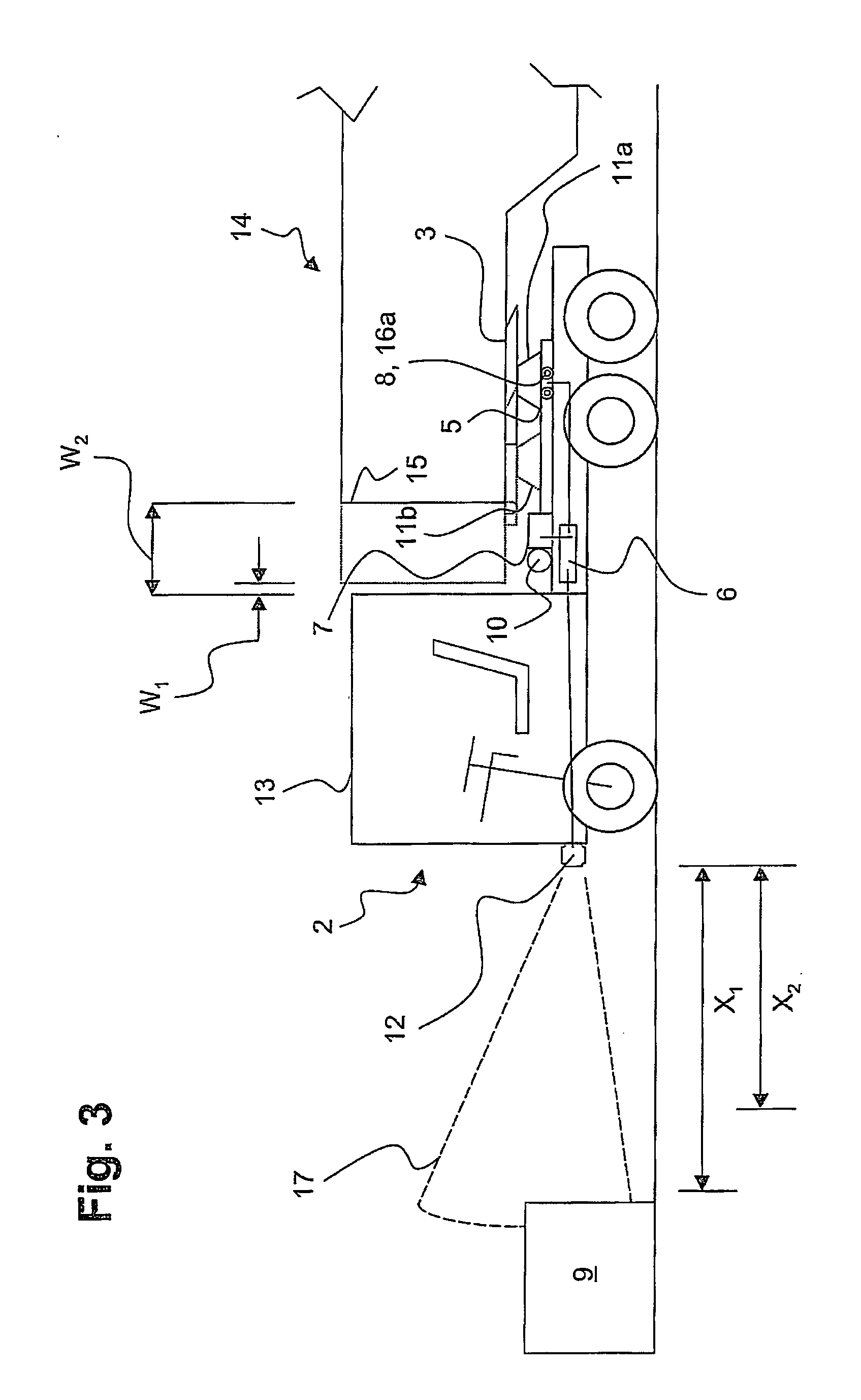
[0009]When the vehicle is traveling at high Autobahn speeds, the semi-trailer will be drawn close to the tractor cab, by means of the displacement device, wherewith the gap between the cab and the front of the semi-trailer will be held at its minimum length. This will minimize vortex formation and thereby will minimize fuel consumption. In the event of a sudden steering maneuver, the fixing of the carriage will be released, and the carriage will be displaced rearward on the guide rails. Using the inventive method, the road path ahead of the vehicle is monitored and obstacles in that path are detected. In this way it is possible to increase the length of the gap between the cab and the front of the semi-trailer even before the driver reacts.
[0010]Preferably the method of achieving this is that, when a prescribed first reaction distance to the obstacle is reached, the control device switches the motorized drive unit and / or the adjusting member into a readiness state. If the driver then initiates intense braking, possibly accompanied by a strong steering maneuver, the rearward displacement of the carriage can be effected without a time delay.
[0013]Advantageously, the carriage will be fixed in the rearward position by means of the adjusting member. In particular, additional security can be achieved if locking pieces disposed on the adjusting member form-interlockingly engage the guide rails, wherewith the carriage will not be exclusively held in place by the motorized drive unit.

Problems solved by technology

However, with this arrangement there is a problem in that when negotiating a curve of relatively short radius the semi-trailer can swing past the cab under conditions of minimization of the gap between the tractor and semi-trailer, and thereby a corner of the semi-trailer is apt to strike against the cab.
This problem also tends to arise in situations of panic braking sudden intense braking without compensating maneuvers; the panic braking can be taken into account by evaluation of a braking signal which is input to the control device and converted into an actuation of the displacement device to bring about extremely rapid rearward movement of the carriage so as to increase the length of the gap.
However, in practice it has been found that inputs in the form of braking signals and vehicle speed signals are not well suited to timely respond to panic braking.
The reaction times required for the control system are extremely short, often insufficient for the system to timely displace the fifth wheel coupling into a rearward position and thereby establish the necessary distance between the cab and the front of the semi-trailer.

Method used


Image

  • Method and control system for a displacement device, with distance measurement in order to detect obstacles
  • Method and control system for a displacement device, with distance measurement in order to detect obstacles
  • Method and control system for a displacement device, with distance measurement in order to detect obstacles

Examples


Embodiment Construction

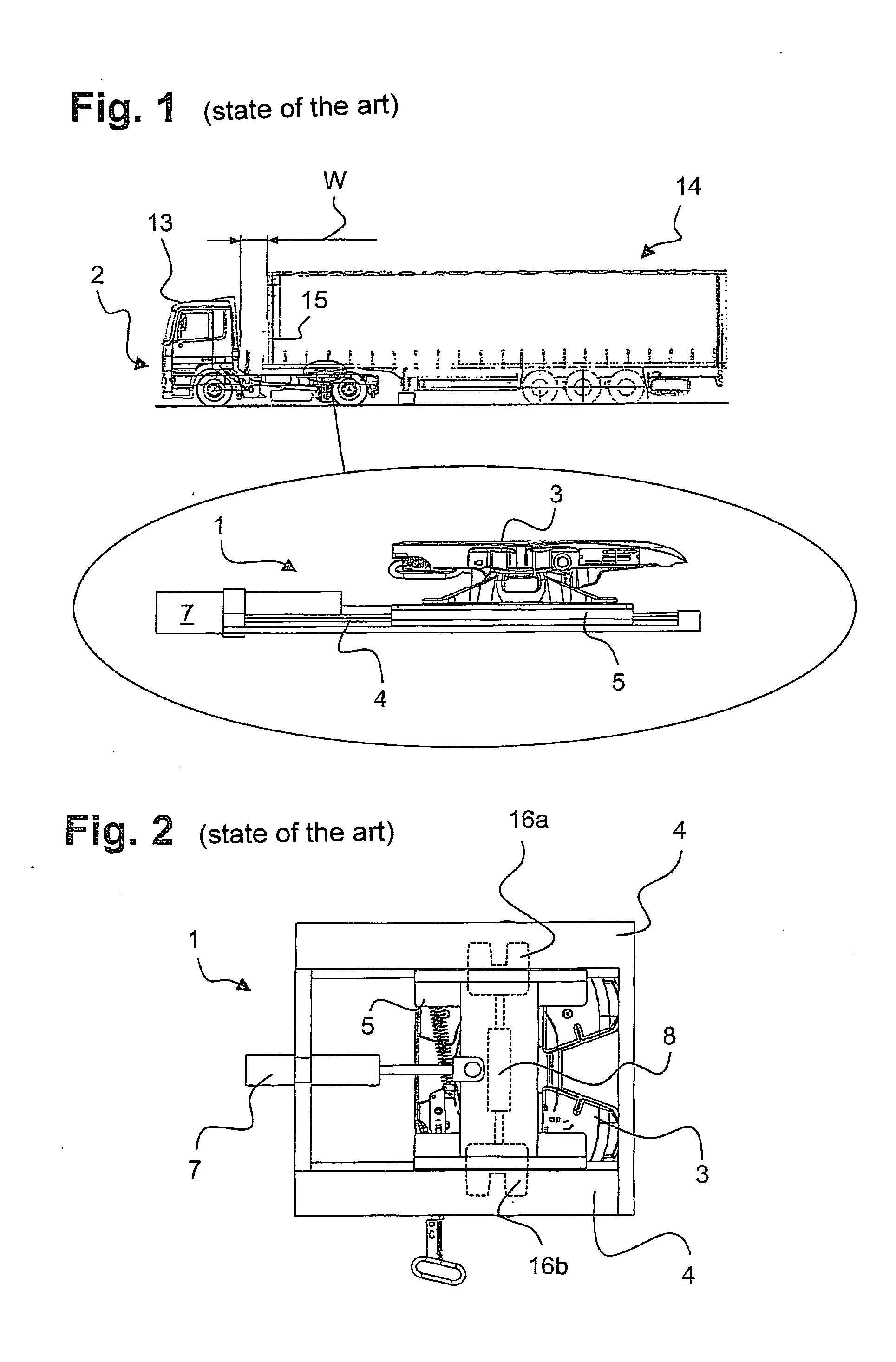
[0022]FIG. 1 is a schematic lateral view of a tractor and semi-trailer combination with a tractor vehicle 2 and a semi-trailer 14 mechanically coupled to the tractor. The mechanical connection between the vehicles 2 and 14 is accomplished via a fifth wheel coupling 3 which is disposed on a carriage 5 and which can be displaced in the longitudinal direction of the tractor vehicle on two parallel guide rails 4 disposed at a mutual distance. The displacement of the fifth wheel coupling 3 occurs during travel of the vehicle, via a special motorized drive unit 7 in the form of a hydraulic cylinder, and serves in particular to adjust the length of the gap W between the rear side of the tractor cab 13 and the front 15 of the semi-trailer.

[0023]The displacement device 1 is illustrated in an enlarged bottom view in FIG. 2. An adjusting member 8 disposed perpendicularly to the guide rails 4 is disposed on the carriage 5; locking pieces 16a, 16b which form-interlockingly engage complementary r...


PUM


Abstract

A method and a system for control of a displacement device for a fifth wheel coupling which coupling is disposed on a tractor vehicle are described, wherein the displacement device has a lower structure having at least one guide rail oriented in the direction of travel, a movable carriage which supports the fifth wheel coupling and engages the guide rail(s), and a control device connected to a motorized drive unit for displacing the carriage and also connected to an adjusting member for fixing the carriage with respect to the guide rail(s). The underlying problem of the invention was to devise a method and a control system whereby timely establishment of a sufficiently long gap between the tractor and the associated semi-trailer is possible. One means by which this problem is solved is with a method wherein distance measurement is carried out to detect an obstacle disposed ahead of the tractor, and the measurement signal is processed in the control device to yield a control signal, which is employed to actuate the motorized drive unit and / or the adjusting member.

Description

FIELD OF INVENTION[0001]The invention relates to a method for controlling a displacement device for a fifth wheel coupling disposed on a tractor vehicle, according to the features in the claims. The invention further relates to a particularly suitable control system for carrying out the inventive method for a displacement device.BACKGROUND OF THE INVENTION[0002]A displacement device of the general type contemplated is known, e.g. from DE 10 2005 060124 A1. With the aid of a motorized drive unit a carriage bearing the fifth wheel coupling can be displaced in the longitudinal direction of the tractor vehicle on two parallel guide rails, and can be locked in a prescribed position. When the vehicle is traveling at rapid Autobahn speeds without appreciable curves, it is desirable for the fifth wheel coupling to be positioned as close as possible to the tractor cab, in order to minimize the gap between the cab and the front of the semi-trailer and thereby minimize vortex formation in this...

Claims


Application Information

Patent Timeline
Patent Type & Authority Applications(United States)
IPC IPC(8): G06F7/00B60D1/44
CPCB60R11/04B62D53/0814B60R2011/004
Inventor ALGUERA, JOSE MANUEL
Owner JOST WERKE
Learn More