Apparatus for ligating living tissues

a technology for living tissues and ligating devices, applied in the field of ligating devices, can solve the problems of increasingrequiring a lot of time, and requiring a large amount of time, and achieves the effects of reducing the number of components, facilitating the manipulation of the attachment clip, and reducing the manufacturing cos

Inactive Publication Date: 2007-05-29
OLYMPUS CORP +1
View PDF16 Cites 263 Cited by
  • Summary
  • Abstract
  • Description
  • Claims
  • Application Information

AI Technical Summary

Benefits of technology

[0011]The present invention has been developed in consideration of the above-described circumstances, and an object thereof is to provide a ligating apparatus in which a clip is directly attached to a manipulating wire, the number of components is thereby decreased in an engaging portion of the clip and manipulating wire, the manufacturing cost is reduced, and an attachment manipulating of the clip is facilitated during manufacturing.

Problems solved by technology

Thereby, the number of components increases, and the manufacturing cost increases disadvantageously.
In this case, since the conventional clip apparatus has an engaging component between the clip and the manipulating wire, much time is required in the attachment manipulating of the clip, and the manipulating is very laborious.

Method used


Image

  • Apparatus for ligating living tissues
  • Apparatus for ligating living tissues
  • Apparatus for ligating living tissues

Examples


first embodiment

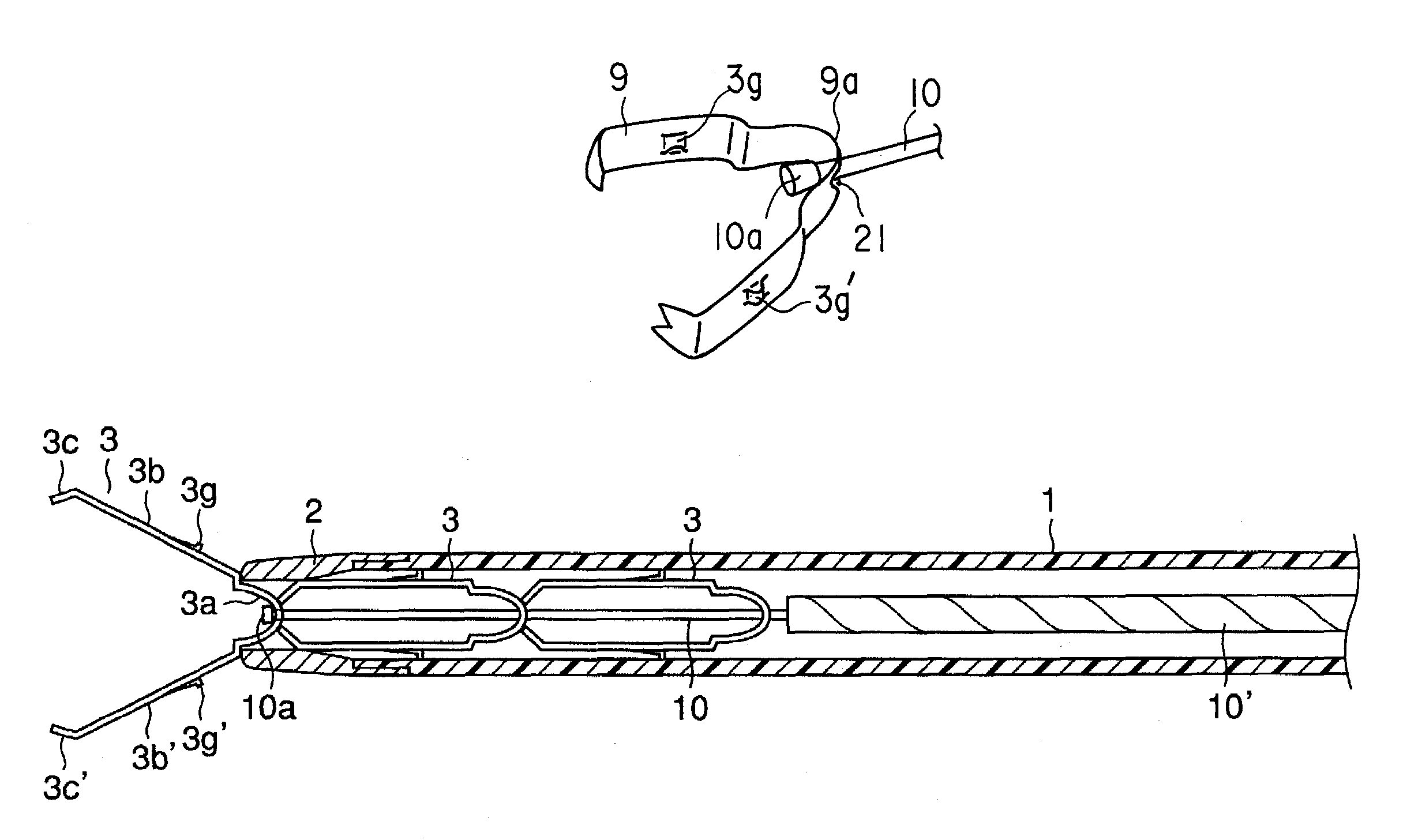
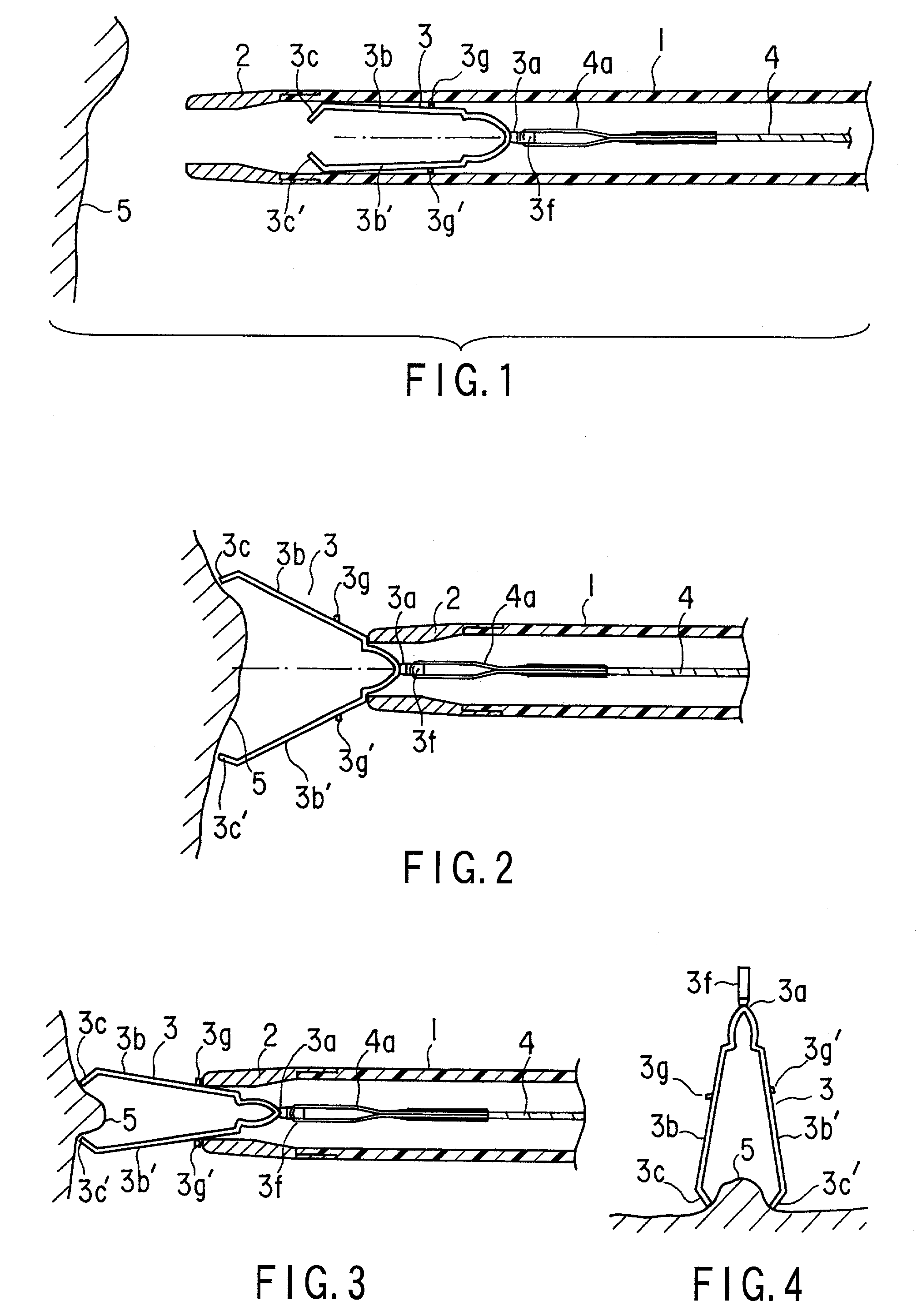
[0057]FIGS. 1 to 6 show a first embodiment, and FIGS. 1 to 3 are longitudinal side views of a tip end in a ligating apparatus. An introducing tube 1 has flexibility such that the tube can be inserted in a channel of an endoscope, and a tip-end chip 2 is disposed in the tip end of the introducing tube 1. The tip-end chip 2 is welded, bonded, or pressed, and fixed to the tip end of the introducing tube 1. A manipulating wire 4 is inserted in the introducing tube 1 in such a manner that the wire can freely advance or retreat, and a clip 3 is disconnectably connected to the tip end of the manipulating wire 4 so that the clip can freely project or retract with respect to the tip end of the introducing tube 1.

[0058]The introducing tube 1 is a coil sheath whose inner and outer surfaces with a metal wire (such as stainless steel) having a circular section closely wound therearound have concaves / convexes. Through such a structure, even when a force for compressing the sheath is applied to th...

second embodiment

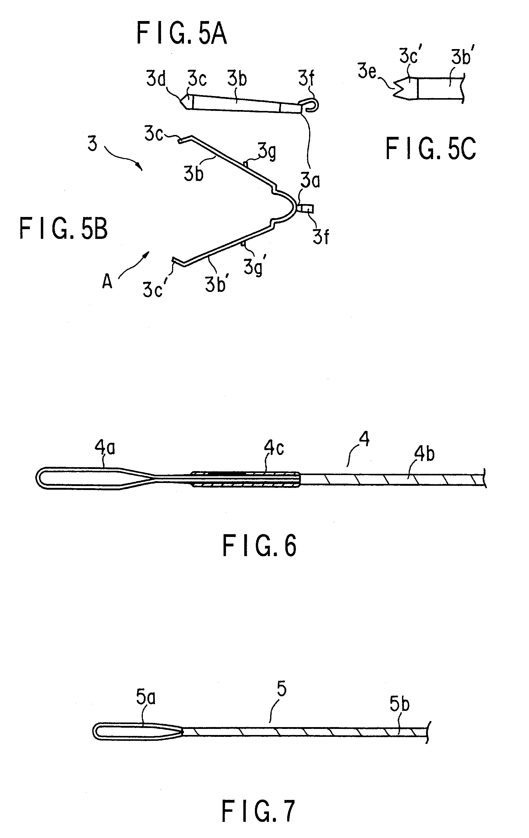
[0079]FIGS. 7 and 8A to 8J show a FIG. 7 is a side view of the tip end of the manipulating wire, and FIGS. 8A to 8J show a manufacturing method of the manipulating wire.

[0080]The wire having the closed loop portion in the tip end as described in the first embodiment is known in Jpn. Pat. Appln. KOKAI Publication No. 2000-271146.

[0081]The loop wire forming a closed loop is joined to the tip end of the manipulating wire via a joint pipe. However, in this structure, the joint pipe for joining the manipulating wire to the loop wire is surely required.

[0082]On the other hand, it is already known that the core wire of the twined manipulating wire is used as the loop wire and the closed loop is formed. However, the joint pipe is required for joining the loop wire to the manipulating wire.

[0083]Thereby, the number of components increases, and accordingly the number of assembly steps by the joining manipulating such as welding, bonding, and caulking also increases. Moreover, there is a prob...

fourth embodiment

[0107]The action of the fourth embodiment will next be described.

[0108]When the holding portions 3c, 3c′ are brought close to the target tissue 5, the manipulating wire 4 is drawn. The arm portions 3b, 3b′ of the clip 8 bent in the extending / opening direction engage with the tip end of the tip-end chip 2. Here, when the holding portions 3c, 3c′ are pressed onto the target tissue 5 and the manipulating wire 4 is further drawn, the arm portions 3b, 3b′ of the clip 8 are pulled in the tip-end chip 2, the holding portions 3c, 3c′ are closed, and the target tissue 5 can be held. Furthermore, when the manipulating wire 4 is drawn, the loop wire 4a is ruptured. A force of 1 to 5 kg is applied to the loop wire 4a during ligating with the clip 8. The dimension is set such that the loop wire 4a is ruptured with the application of the force.

[0109]When the loop wire 4a is ruptured, the clip 8 is disengaged from the manipulating wire 4, and the clip 3 can be fastened in the living tissue.

[0110]A...


PUM


Abstract

A ligating apparatus includes an introducing tube which can be inserted in a living body cavity, a manipulating wire inserted in the introducing tube in such a manner that the manipulating wire can freely advance or retreat, a clip which is directly joined to a tip end of the manipulating wire, which has a holding portion formed in a tip end of an arm portion extending from the base end, and which has an extending/opening property, and engaging structure disposed in at least one of the base end of the clip and the tip end of the manipulating wire, wherein at least one of the engaging means is deformed and releases engaging of the clip and the manipulating wire, when the clip engages with the tip end of the introducing tube, and a force for detaching the base end of the clip from the tip end of the manipulating wire is applied.

Description

CROSS-REFERENCE TO RELATED APPLICATIONS[0001]This application is based upon and claims the benefit of priority from the prior Japanese Patent Application(s) No. 2001-28483, filed Feb. 5, 2001 and No. 2001-319657, filed Oct. 17, 2001, the entire contents of which are incorporated herein by reference.BACKGROUND OF THE INVENTION[0002]1. Field of the Invention[0003]The present invention relates to a ligating apparatus which is endoscopically inserted in a living body cavity and holds living tissues with a clip.[0004]2. Description of the Related Art[0005]Known examples of an apparatus for ligating living tissues are described in Jpn. Pat. Appln. KOKAI Publication No. 60-103946 and Jpn. UM Appln. KOKAI Publication Nos. 62-170010 and 2-6011, and the like.[0006]In Jpn. Pat. Appln. KOKAI Publication No. 60-103946, a clip is attached to a manipulating wire via an eye disposed in a base end of the clip and a hook disposed in a tip end of the manipulating wire. A clip tightening ring is attach...

Claims


Application Information

Patent Timeline
Patent Type & Authority Patents(United States)
IPC IPC(8): A61B17/122A61B17/08A61B17/064A61B17/10A61B17/12A61B17/128A61B17/28
CPCA61B17/1227A61B17/1285A61B17/0643A61B17/122A61B2017/2905A61B2017/2927
Inventor MURAMATSU, JUNICHIKOBAYASHI, TSUKASASUZUKI, TAKAYUKIYAMAMOTO, TETSUYA
Owner OLYMPUS CORP
Why Eureka
Try Eureka