3D imaging system

a 3d imaging and image technology, applied in the field of cameras, can solve the problems of long turn-on and turn-off times of these photosurfaces, and achieve the effect of simplifying construction and control

Inactive Publication Date: 2007-05-29
MICROSOFT INT HLDG BV
View PDF21 Cites 270 Cited by
  • Summary
  • Abstract
  • Description
  • Claims
  • Application Information

AI Technical Summary

Benefits of technology

[0019]To provide proper control of the amounts of light reaching the 3D camera and the imaging camera, the 3D imager comprises a system that controls the amount of light reaching the imaging camera from the taking lens independently of the amount of light reaching the 3D camera.
[0020]Preferably, the 3D camera comprises at least two irises. A first iris of the at least two irises controls the amount of visible light collected by the taking lens that reaches the imaging camera. A second iris controls either the amount of IR light collected by the taking lens that reaches the 3D camera or the total amount of IR and visible light collected by the taking lens that enters the 3D imager. As a result, the 3D imager can be adjusted to control independently amounts of light reaching the imaging camera and the 3D camera from a scene being imaged with the 3D imager. Therefore, subject to a level of illumination of the scene, a 3D imager, in accordance with a preferred embodiment of the present invention, is adjustable to simultaneously optimize the amounts of light from the scene that reach its 3D and imaging cameras.
[0021]In accordance with some preferred embodiments of the present invention all photosurfaces comprised in the 3D camera are gated with a same single fast shutter. This substantially simplifies the construction and control of the 3D imager. Preferably the 3D camera comprises three photosurfaces, a distance photosurface, a background photosurface and a normalized photosurface. The three photosurfaces are independently controllable to the turned on and off. Preferably, all light transmitted from the taking lens to the 3D camera passes through the single fast shutter. After passing through the shutter, portions of the light arc directed to each of the three photosurfaces, for example by a prism. Preferably, the prism is a totally internal reflection (TIR) prism. At any given time, to determine which of the photosurfaces is gated by the fast shutter, all photosurfaces except a photosurface that is to be gated by the fast shutter are shut off.

Problems solved by technology

However, turn-on and turn-off times of these photosurfaces are generally much too long to enable gating the photosurfaces for the purposes of accurate distance measurements by turning them on and off.

Method used


Image

  • 3D imaging system
  • 3D imaging system
  • 3D imaging system

Examples


Embodiment Construction

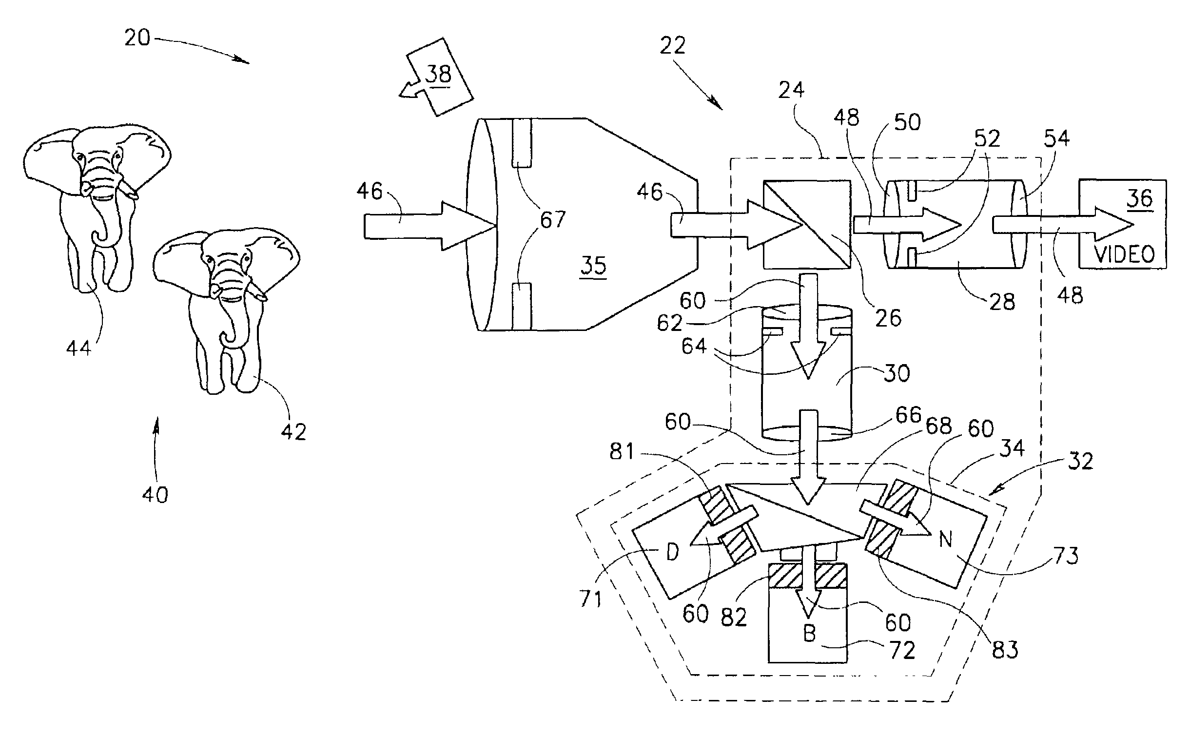
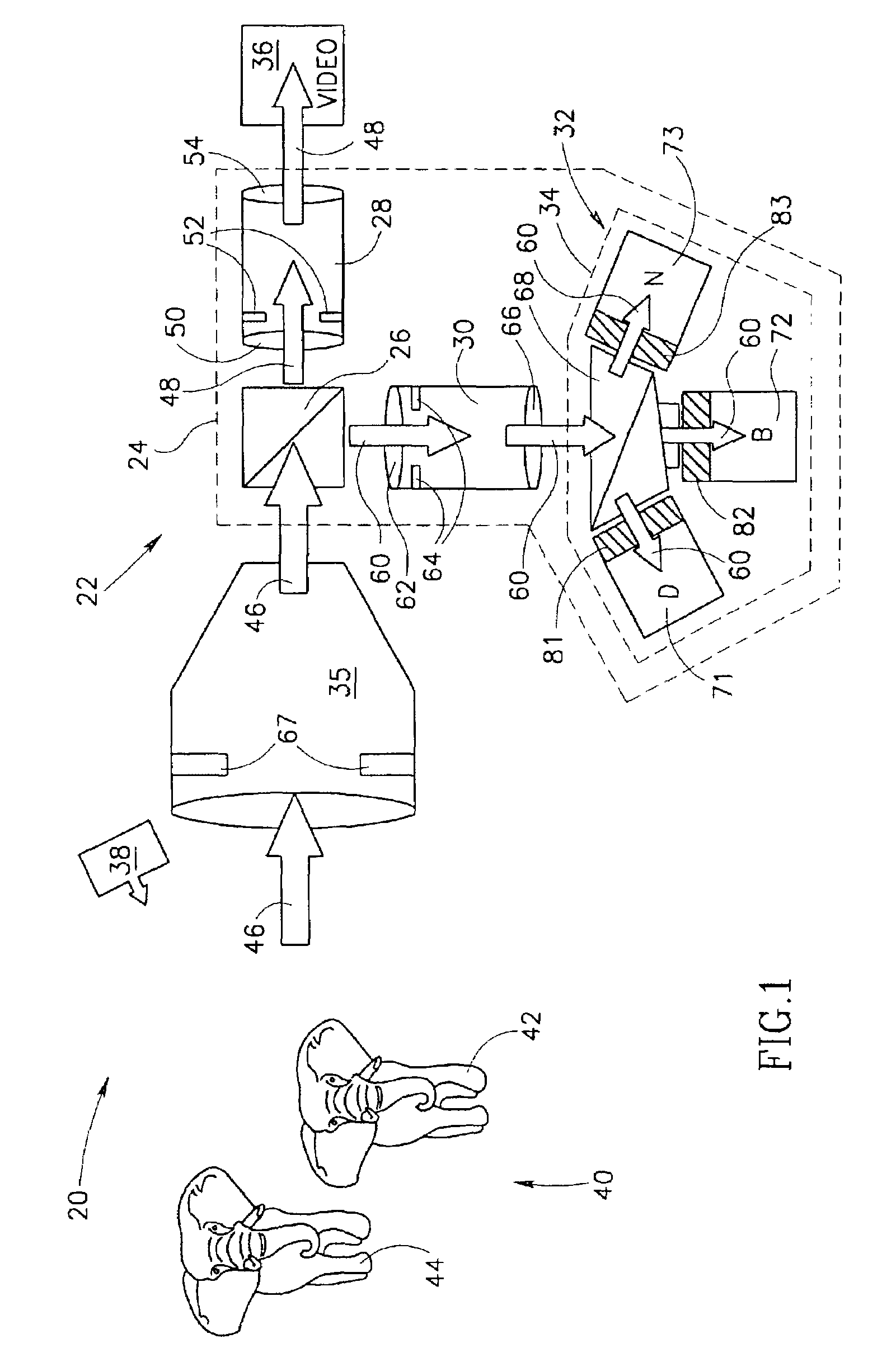
[0051]FIG. 1 schematically shows a 3D imager 20 comprising a 3D module 22, in accordance with a preferred embodiment of the present invention, shown inside dashed boundary 24. 3D module 22 comprises a beam splitter 26, two refocusing lens system 28 and 30, referred to as “refocusers”28 and 30, and a 3D camera 32 having components shown inside a dashed boundary 34. 3D module 22 is coupled to a taking lens system 35 and an imaging camera 36, which is shown by way of example as a video camera. Preferably, video camera 36 is a color video camera. Taking lens 35 and video camera 36 may be any suitable taking lens and video camera, for example a CCD or CMOS camera, readily available on the commercial market. A pulsed light source 38 radiates pulse trains of, preferably IR light pulses, to illuminate scenes being imaged with 3D imager 20. 3D imager 20 is shown, by way of example, imaging a scene 40 having two elephants 42 and 44.

[0052]Visual light and IR light from IR source 38 that is ref...


PUM


Abstract

An optical imaging system comprising: a taking lens system that collects light from a scene being imaged with the optical imaging system; a 3D camera comprising at least one photosurface that receives light from the taking lens system simultaneously from all points in the scene and provides data for generating a depth map of the scene responsive to the light; and an imaging camera comprising at least one photosurface that receives light from the taking lens system and provides a picture of the scene responsive to the light.

Description

RELATED APPLICATIONS[0001]The present application is a U.S. national application of PCT / IL99 / 00490, filed Sep. 8, 1999.FIELD OF THE INVENTION[0002]The invention relates to cameras that provide an image of a scene and measurements of distances to regions in the scene.BACKGROUND OF THE INVENTION[0003]3D cameras that provide distance measurements to objects and points on objects that they image are well known in the art. Gated 3D cameras comprise a photosensitive surface, such as a CCD or CMOS camera, hereinafter referred to as a “photosurface”, and a gating means for gating the camera open and closed, such as an electro-optical shutter or a gated image intensifier. To image a scene and determine distances from the camera to objects in the scene, the scene is generally illuminated with a train of light pulses radiated from an appropriate light source. Generally, the radiated light pulses are infrared (IR) light pulses. For each radiated light pulse in the train, following an accurately...

Claims


Application Information

Patent Timeline
Patent Type & Authority Patents(United States)
IPC IPC(8): H04N9/04H04N5/225G01S7/481G01S17/18G01S17/86G01S17/894H04N13/02
CPCG01S7/4812G01S17/023G01S17/107G01S17/89H04N5/2226G01S17/18G01S17/86G01S17/894
Inventor IDDAN, GAVRIEL J.YAHAV, GIORABRAUN, ORI J.
Owner MICROSOFT INT HLDG BV
Why Eureka
Try Eureka