Recording medium, its controller and controlling method

a controller and control method technology, applied in the field of recording mediums, can solve the problems of difficult to change the size of the sector, the number, the limit of the interval between tracks, etc., and achieve the effect of simple structure and easy to obtain a clock signal

Inactive Publication Date: 2007-05-29
PANASONIC CORP
View PDF18 Cites 14 Cited by
  • Summary
  • Abstract
  • Description
  • Claims
  • Application Information

AI Technical Summary

Benefits of technology

[0174]The oscillator which provides a reference is incorporated within the control apparatus for the recording medium according to the present invention, and as the output signal from the oscillator is frequency-divided based on the volume of data per segment read out from the recording medium, synchronizati

Problems solved by technology

When tracking is to be performed using primary diffracted light from the ditch as in the above-mentioned prior art example described earlier, there is a limitation on intervals between tracks (track pitch) where only the ditch is used as the data recording area.
The capacity of an optical disk is determined by the total number of sectors in each zone and the optical disk has physical zone and sector structures which are pre-formatted, and therefore, it is extremely difficult to change the size of the sectors, the number of the sectors and the like on the optical disk.
Hence, even though it becomes possible to record and reproduce at an even higher density owing to an improved characteristic of a recording film of an optical disk realized by technological advance, it is not possible to increase the data capacities of optical disks which comply with an existing standard.
This poses a problem that in the event that high-density optical disks are commercialized in accordance with the new standard, it would not be possible to record data in a new optical disk or reproduce data from a new optical disk using disk drives which are already available in the market since the disk drives already available in the market would not be compatible with the new format.
Hence, the problem that it is not possible to enhance a density with the disk drives already available in the market has heretofore been considered as a problem which is strongly relevant to other problems (problems regarding optical constants such as NA and λ) and which can not be solved.
However, as described earlier, since there are pre-formatted zones and addresses in a prior art optical disk described above, it is not possible to change the sizes of sectors which are each associated with each o

Method used


Image

  • Recording medium, its controller and controlling method
  • Recording medium, its controller and controlling method
  • Recording medium, its controller and controlling method

Examples


embodiment 1

[0236]FIGS. 1 through 14 show a magneto-optical disk and a recording apparatus, a reproducing apparatus, a recording method or a reproduction method according to the present invention.

[0237]While the embodiments herein described are directed to a magneto-optical disk and a recording apparatus, a reproducing apparatus, a recording method or a reproduction method for the same, applications of the present invention are not limited to a magneto-optical disk, and applications to any desired recording medium are possible.

1)>

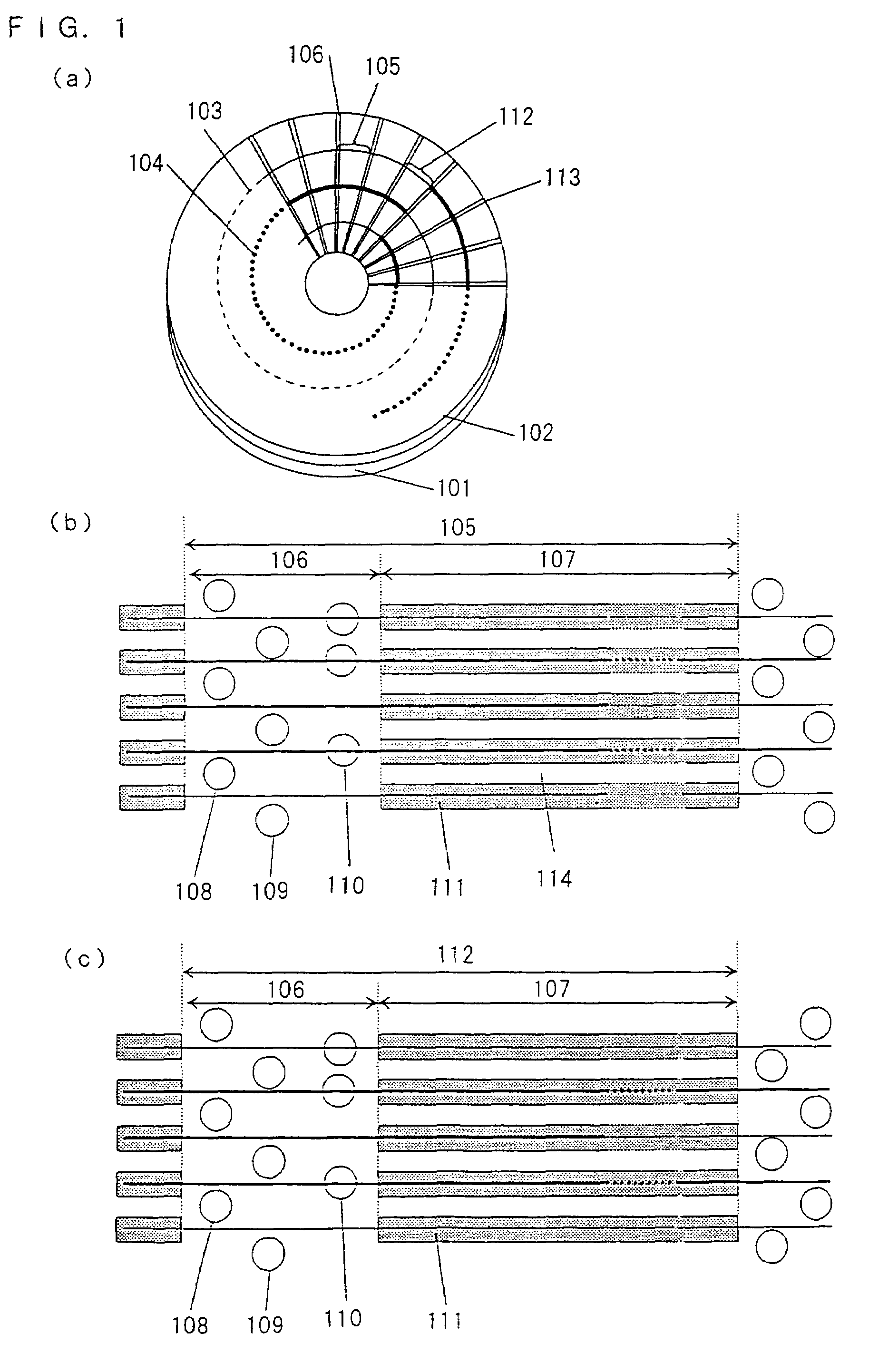
[0238]Part (a) of FIG. 1 shows a general overall structure of a magneto-optical disk according to an embodiment 1 of the present invention.

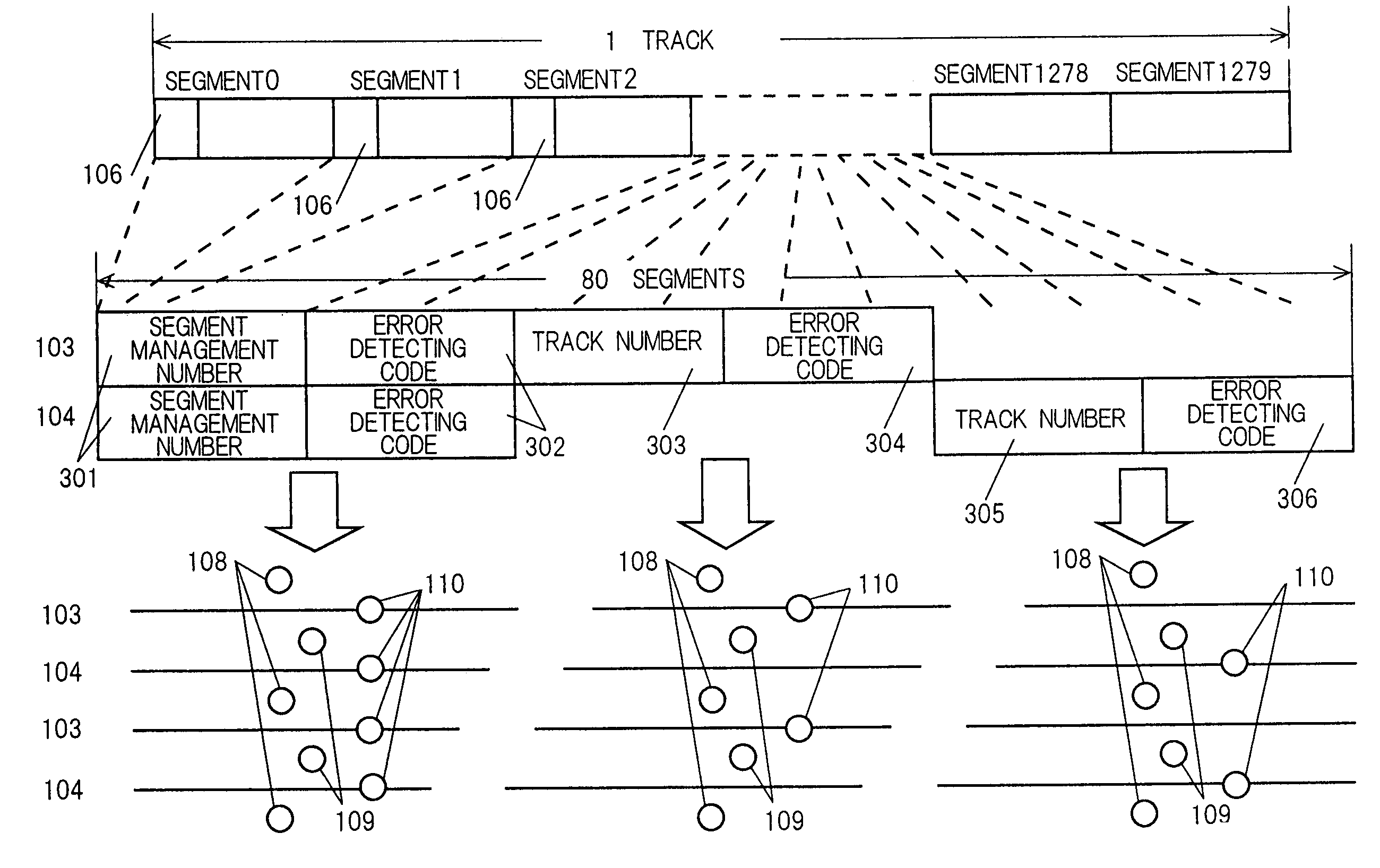
[0239]In part (a) of FIG. 1, denoted at 101 is an optical disk substrate, denoted at 102 is a recording film (a reproduction layer 13, an intermediate layer 14 and a recording layer 15 in FIG. 7), denoted at 103 is a first recording track, denoted at 104 is a second recording track which is next to the first recording track, denoted...

embodiment 2

[0398]A magneto-optical disk, and a recording apparatus, a reproducing apparatus, a recording method and a reproduction method for the same according to the present invention will now be described with reference to FIGS. 15 through 17.

[0399]The magneto-optical disk, and the recording apparatus, the reproducing apparatus, the recording method and the reproduction method for the same according to the embodiment 2 are basically the same as the magneto-optical disk and the like according to-the embodiment 1.

[0400]The magneto-optical disk according to the embodiment 2 is different from the magneto-optical disk according to the embodiment 1 in that the magneto-optical disk according to the embodiment 2 comprises information regarding a defective segment (which is a segment in which data cannot be correctly recorded or reproduced) and a spare segment which complements a defective segment.

[0401]In a similar fashion, the recording apparatus, the reproducing apparatus, the recording method an...

embodiment 3

[0436]Part (a) of FIG. 18 shows a general overall structure of the magneto-optical disk according to the

[0437]In part (a) of FIG. 18, denoted at 1801 is an optical disk substrate, denoted at 1802 is a recording film (the reproduction layer 13, the intermediate layer 14 and the recording layer 15 in FIG. 7), denoted at 1803 is a first recording track, denoted at 1804 is a second recording track which is next to the first recording track, denoted at 1805 are segments obtained by dividing the first recording track 1803 and the second recording track 1804 into 1280 pieces, denoted at 1806 and 1813 are pre-pit areas (pre-formatted areas) which contain start pits, servo pits for tracking and address pits which express position information on the disk.

[0438]As shown in the drawing, the first recording track 1803 and the second recording track 1804 are spiral areas which start and end at the pre-pit areas 1813: When the spiral recording tracks are traced from an inner round toward an outer ...


PUM


Abstract

A recording medium which has a high recording density and realizes a short search time is provided. The recording medium according to the present invention is a recording medium which comprises addresses indicative of positions on the recording medium and which is for recording or reproduction using sectors as data rewrite units or data read units, and starting positions of said addresses and starting positions of said sectors are different in the recording medium.

Description

[0001]CROSS-REFERENCE TO RELATED APPLICATION[0002]This application is a Section 371 of International Application No. PCT / JP01 / 09652, filed Nov. 2, 2001, the disclosure of which is incorporated herein by reference.TECHNICAL FIELD[0003]The present invention relates to a recording medium which has pre-formatted addresses or segments, a recording apparatus and a reproducing apparatus for such a recording medium (control apparatus), and a recording method and a reproduction method for such a recording medium (control method).BACKGROUND ART[0004]While the recent years have seen a use of an optical disk as a storage medium for a large-volume data file, music, video and the like, there still is an ongoing endeavor to increase a capacity of an optical disk in an attempt to use optical disks for an even more diversified applications.[0005]A method generally used for efficient accessing of a large-capacity optical disk is to divide recording data into sectors having a data size of a constant u...

Claims


Application Information

Patent Timeline
IPC IPC(8): G11B7/00G11B7/007G11B11/105G11B20/12G11B20/14G11B20/18G11B27/19G11B27/24
CPCG11B20/1217G11B20/1258G11B20/1403G11B20/1883G11B27/19G11B27/24G11B7/007G11B7/00745G11B11/10565G11B2020/1232G11B2020/1267G11B2020/1274G11B2020/1294G11B2220/20G11B2220/2525G11B2220/2545G11B2220/2562G11B7/00
Inventor HINO, YASUMORIMATSUMOTO, TOSHIO
Owner PANASONIC CORP
Why Eureka
Try Eureka