
Compression packaged image transmission for telemicroscopy

a videographic imaging and compression package technology, applied in the field of remote operation and viewing of videographic imaging systems, can solve the problems of inability to support a large pathology staff, lack of bandwidth to allow video transmission at anything approximating real-time, and certain compromises between channel capacity and image quality

Inactive Publication Date: 2007-05-29
CARL ZEISS MICROIMAGING AIS
View PDF82 Cites 73 Cited by
  • Summary
  • Abstract
  • Description
  • Claims
  • Application Information

AI Technical Summary

Benefits of technology

"The present invention relates to improving the quality and speed of transmitting images in telemedicine and telepathology systems. The invention uses statistical redundancy removal techniques to compress video data and reduce the amount of data transmitted over a network, while maintaining image quality. This allows for faster transmission times and better utilization of network bandwidth. The invention also addresses the issue of limited bandwidth availability and proposes a solution to improve the quality of the transmitted images while maintaining transmission speed. Overall, the invention improves the efficiency and flexibility of telemedicine and telepathology services, making them more accessible to small to medium sized hospitals and remote areas of the country where specialty medical staff is limited."

Problems solved by technology

Likewise, small to medium sized hospitals, which may not be able to support a large pathology staff incorporating the many subspecialties required for full coverage, are able to avail themselves of the same quality of pathology services that one might find in a major urban hospital.
Broadband systems (like ATM) allow enhanced channel capacity but still suffer from a lack of sufficient bandwidth to allow video transmissions at anything approximating real-time.
Because of these limitations, conventional telemicroscopy systems have had to make certain compromises between channel capacity and image quality.
Conversely, when transmission speed is an overriding concern, image quality necessarily suffers.
Before telepathology services become truly viable, image transmission must operate at bit rates of only a few hundred kilobits or a few megabits per second, which can only be achieved through rather large compression of the data.

Method used


Image

  • Compression packaged image transmission for telemicroscopy
  • Compression packaged image transmission for telemicroscopy
  • Compression packaged image transmission for telemicroscopy

Examples


Embodiment Construction

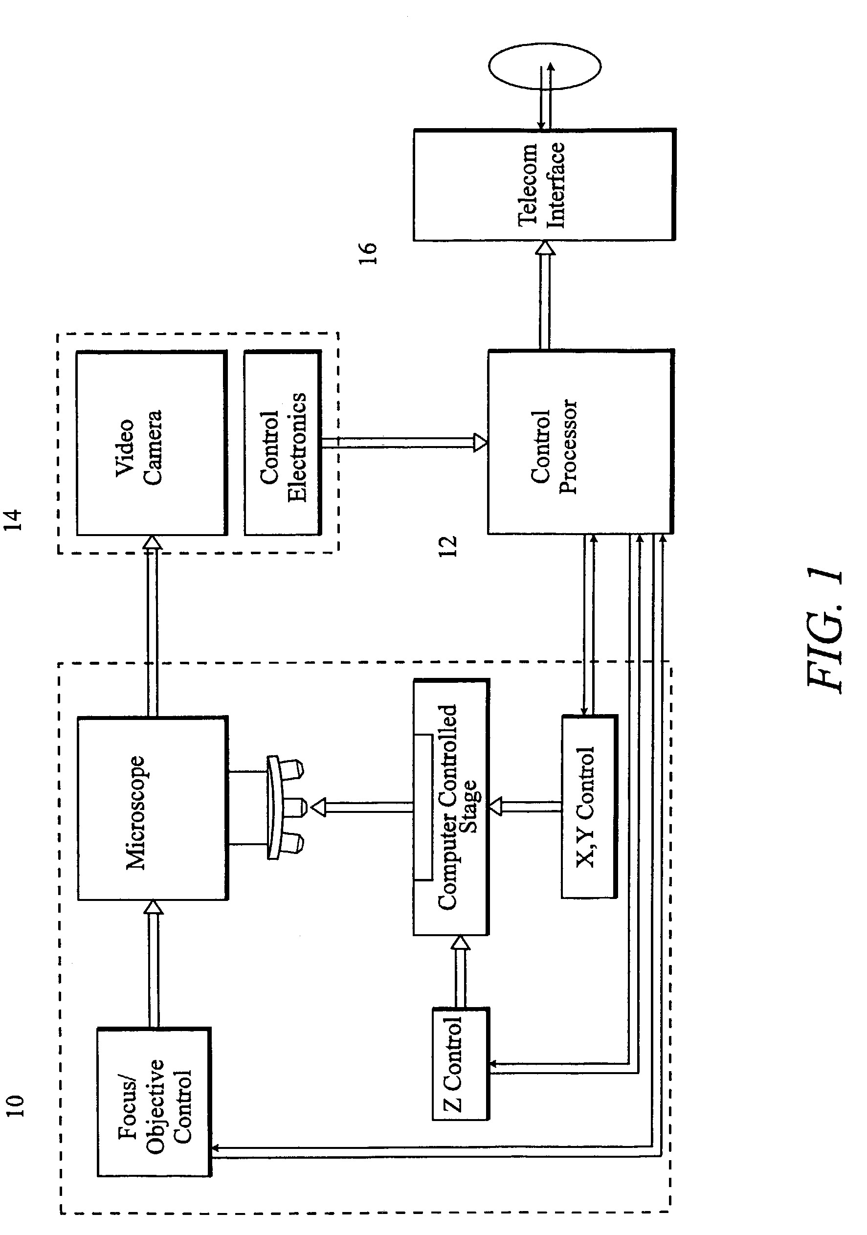
[0017]In order to gain a complete understanding of the compression packaged image transmission system and method of the present invention, it will be useful to examine how the system might function in the context of a typical telepathology procedure. During the course of a surgical intervention, as a surgeon is preparing to perform an invasive procedure, the surgeon will typically remove a sample of tissue from a patient and forward the tissue sample to the hospital's diagnostic laboratory for immediate evaluation. The tissue sample is prepared in conventional fashion and loaded onto the sample stage of an examining microscope, comprising the laboratory's telemicroscopy system, where an image of the tissue sample is captured by a video camera and electronically communicated to a pathologist at a remote site for evaluation. During the initial, or preliminary, evaluation, a pathologist is able to view the tissue sample in macro and is further able to give directions to laboratory pers...


PUM


Abstract

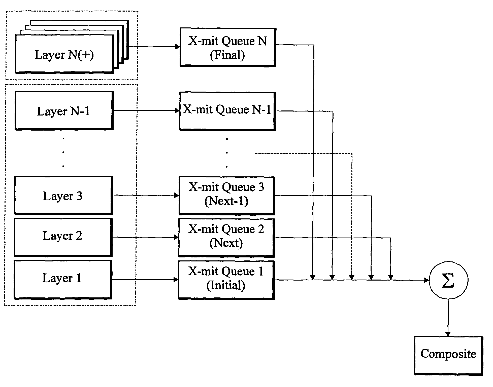
A system and method for visual image compression and transmission offers significant bandwidth conservation while retaining high resolution imaging capability. Videograpic images are decomposed into detail levels, and images are delivered to a remote site display at a level of detail proportional to the perception level of a viewer. Images are transformed, quantized, coded and queued for transmission in accordance with their level of image detail. Image detail layers are transmitted as an inverse function of image displacement speed and as a direct function of image magnification. Images are constructed vertically with each additional queueing layer providing additional image detail. Higher priority layers are lossy encoded, while the lowest priority layers (highest detail levels) are losslessly encoded.

Description

CROSS-REFERENCE TO RELATED APPLICATIONS[0001]This is a continuation of application Ser. No. 09 / 323,371, filed Jun. 1, 1999, now U.S. Pat. No. 6,606,413 which claims benefit of U.S. Provisional Application No. 60 / 087,523, filed Jun. 1, 1998.FIELD OF THE INVENTION[0002]The present invention relates generally to the field of remote operation and viewing of a videographic imaging system and, more particularly, to the acquisition and transmission of images useful in the field of telemedicine to effect remote site diagnostic and consultation procedures.BACKGROUND OF THE INVENTION[0003]The digital revolution has intruded in almost every sphere of modern electronic communications and has given rise to applications and abilities that were not even considered prior to the introduction of the small platform computer system in the late 1960's and its subsequent development through the 70's, 80's and 90's. Although totally pervasive in every aspect of society and sector of the economy, the digit...

Claims


Application Information

Patent Timeline
Patent Type & Authority Patents(United States)
IPC IPC(8): G06K9/36H04N7/14G06K9/00G06T9/00
CPCG06T9/007G16H10/40G16H80/00
Inventor ZEINEH, JACK A.
Owner CARL ZEISS MICROIMAGING AIS
Learn More