Audio encoding device, decoding device, method, circuit, and program

a technology of audio coding and decoding device, applied in the direction of speech analysis, instruments, stereophonic arrangments, etc., can solve the problems of wasting bits used for sending time-warping information, difficulty in pitch contour detection, sound quality deterioration, etc., to improve the sound quality and coding efficiency of the audio coding system, prevent deterioration of sound quality, and evaluate the effect of time-warping

Inactive Publication Date: 2011-11-03
PANASONIC CORP
View PDF4 Cites 27 Cited by
  • Summary
  • Abstract
  • Description
  • Claims
  • Application Information

AI Technical Summary

Benefits of technology

[0063]In the time-warping scheme according to the present invention, a pitch contour is modified based on information of analysis of a harmonic structure of an audio signal, and effectiveness of time warping is evaluated by comparing the harmonic structures before and after time warping in order to make a determination as to whether the time warping should be applied to the corresponding audio frame. This prevents deterioration of sound quality due to inaccuracy in the detected pitch contour information. Furthermore, the time-warping technique according to the present invention improves sound quality and coding efficiency of the audio coding system by utilizing M-S stereo mode information from the transform coding system.
[0064]In addition, a more appropriate range of a pitch change ratio (see the range 86 of the ratios 88 in FIG. 18) is used.
[0065]Then, an appropriate process is performed on the pitch change ratio in such a wider range (see the ratios 88 in FIG. 18) that sound quality is improved.
[0066]In addition, the data amount (for example, an average amount) of codes (see the codes 90 in FIG. 18) obtained by coding of a pitch (see the pitch 822 and the ratio 83 in FIG. 15 and the ratios 88 in FIG. 18) is reduced.

Problems solved by technology

However, there is a problem that the pitch contour detection may be difficult because of change in the amplitude and cycle of a signal.
When time warping is applied based on an inaccurate pitch contour, the sound quality deteriorates and the bits used for sending the time-warping information are wasted.
Currently, there is no method of coding pitch contour information which can work efficiently in the time warping in the conventional techniques.

Method used


Image

  • Audio encoding device, decoding device, method, circuit, and program
  • Audio encoding device, decoding device, method, circuit, and program
  • Audio encoding device, decoding device, method, circuit, and program

Examples


first embodiment

[0126]An encoding device using a dynamic time-warping scheme according to the first embodiment is proposed in the following.

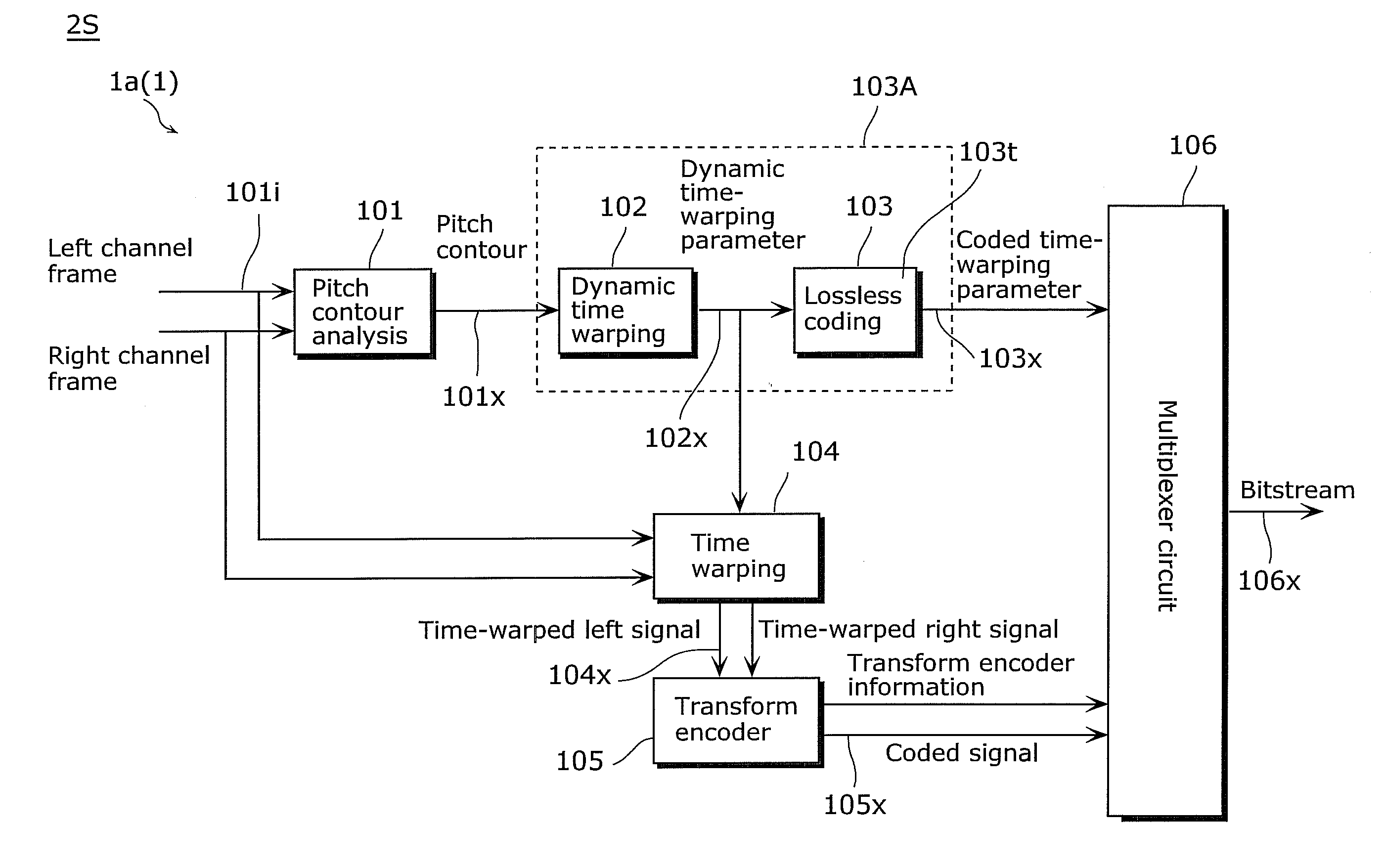
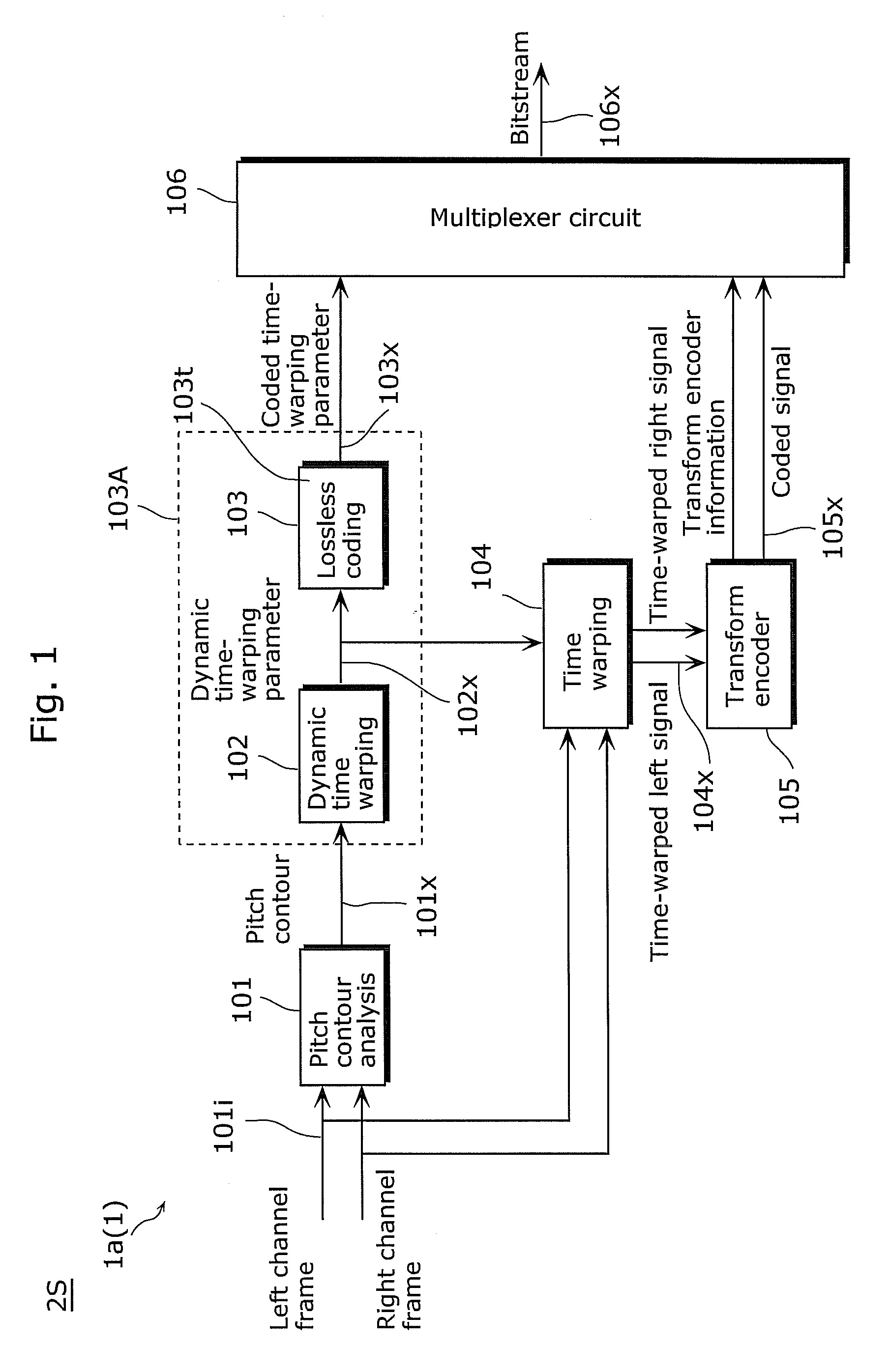
[0127]FIG. 1 illustrates an example of the proposed encoder (encoding device).

[0128]In FIG. 1, one frame of each of a left signal and a right signal is sent to a block 101, which is a pitch contour analysis block. In the block 101 (the pitch contour analysis block (or a pitch contour analysis unit) 101), pitch contours of two channels (left and right channels) are calculated separately. That is, a pitch contour is calculated for each of the channels. The pitch contour detection algorithm described in the conventional techniques, for example, may be used here (in the pitch contour analysis unit 101).

[0129]Next, each of the frames is segmented into M overlapping sections as illustrated in FIG. 8. Then, M pitches are calculated from the M sections within one frame.

[0130]The pitch contours of the left and right channels extracted in the block 101 are sent to a bloc...

second embodiment

[0139]The following describes a method of dynamic time warping of time-warping parameters using a coding scheme with increased efficiency according to the second embodiment.

[0140]As explained in the Technical Problem, pitch detection is difficult because of change in the amplitude and cycle of a signal. Then, inaccuracy in a pitch contour affects performance of time warping if such pitch contour information is directly used for time warping. Since harmonics of a signal are modified in proportion to pitch shifting during time warping, it is necessary to take into account effects of the time warping on the harmonics.

[0141]In the time-warping method according to the second embodiment, a pitch contour is modified on the basis of an analysis of a harmonic structure of an audio signal, so that more efficient dynamic time-warping parameters are generated. The method is composed of three parts.

[0142]In the first part, a pitch contour is modified according a harmonic structure.

[0143]In the s...

third embodiment

[0181]A decoding device using a dynamic time-warping scheme according to the third embodiment is proposed in the following.

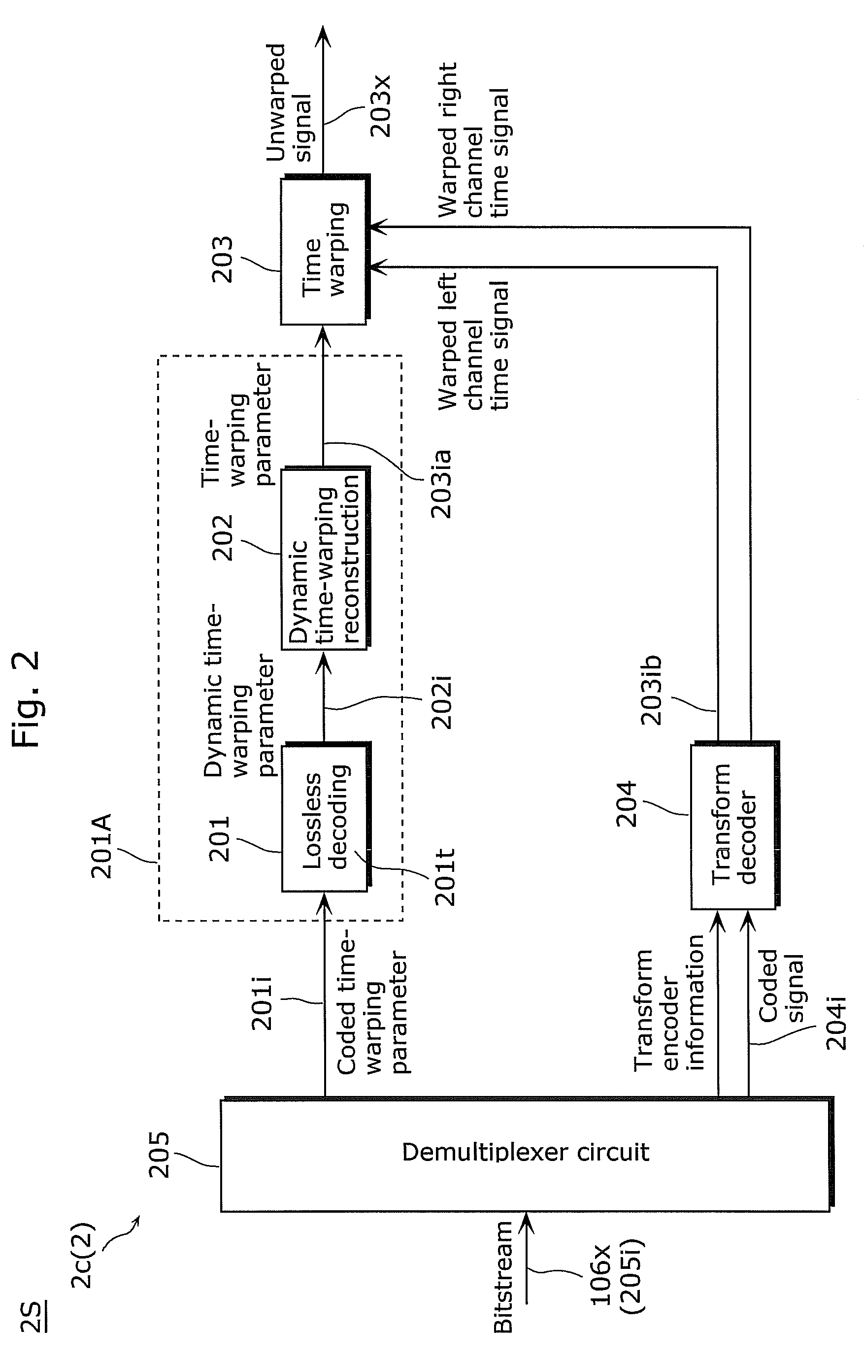
[0182]FIG. 2 illustrates a block diagram of the third embodiment.

[0183]In a block 205, which is a demultiplexer, the input bitstream is separated into the coded time-warping parameters, the coded audio signal, and the relevant transform encoder information.

[0184]The coded time-warping parameters are sent to a block 201, which is a lossless decoding block. In this block, the dynamic time-warping parameters are generated.

[0185]The dynamic time-warping parameters include the flag, the information on positions where time warping is applied, and the corresponding time-warping values Δpi.

[0186]The dynamic time-warping parameters are sent to a block 202, which is a dynamic time warping-reconstruction block. In the block 202, the dynamic time-warping parameters are decoded into the time-warping parameters.

[0187]In a block 204, which is a transform decoder, the coded sig...


PUM


Abstract

Provided is an encoding device (1) including: a pitch contour analysis unit (101) which detects information, a dynamic time-warping unit (102) which generates, based on the information, pitch change ratios (Tw_ratio in FIG. 18) within a range (86) including a range (86a) of the pitch change ratios corresponding to absolute pitch differences of 42 cents or larger; a first lossless coding unit (103) which codes the generated pitch parameters (102x); a time-warping unit (104) which shifts a pitch of a signal according to the information; and a second encoding unit which codes a signal (104x) obtained by the shifting.

Description

TECHNICAL FIELD[0001]The present invention relates generally to transform audio coding systems, and particularly to a transform audio coding system in which a time-warping techniques is used for shifting a pitch frequency of input audio signals to improve coding efficiency and sound quality. The audio coding system can be applied not only to coding of an audio signal but also to coding of a speech signal, and thus can be used in mobile phone communications or a teleconference through telephone or video.BACKGROUND ART[0002]Transform coding technology is designed to code audio signals efficiently. The fundamental frequency of the signal representing human speech varies sometimes. This causes the energy of a speech signal to spread out to wider frequency bands. It is not efficient to code a pitch-varying speech signal using a transform codec, especially in low bitrate. The time-warping technique is used in conventional techniques to compensate effects of variation of pitch as disclosed...

Claims


Application Information

Patent Timeline
Patent Type & Authority Applications(United States)
IPC IPC(8): H04R5/00G10L19/00G10L19/008G10L19/02G10L19/09G10L19/26
CPCG10L19/008G10L19/0212G10L25/90G10L19/265G10L19/09
Inventor ISHIKAWA, TOMOKAZUNORIMATSU, TAKESHICHONG, KOK SENGZHOU, HUANZHONG, HAISHAN
Owner PANASONIC CORP
Why Eureka
Try Eureka