Anchor bolt placement and protection device

a protection device and anchor bolt technology, applied in the direction of buildings, buildings, constructions, etc., can solve the problems of inconvenient placement of anchor bolts, inconvenient installation, and high labor intensity of workers, and achieve the effect of preventing thread contamination

Active Publication Date: 2007-06-05
SMITH JAMES R
View PDF10 Cites 25 Cited by
  • Summary
  • Abstract
  • Description
  • Claims
  • Application Information

AI Technical Summary

Benefits of technology

[0012]In the second embodiment, the anchor bolt placement device is again provided with a tubular projection having an open bottom end and a closed or otherwise terminated top end with a single lateral projection extending integrally and perpendicularly from the open bottom end of the tubular projection. The top surface of the lateral extension is provided with cross-ribs associated with indicia that indicate the proper placement of either a 2″×4″ or 2″×6″ mud sill, and appropriate pre-dilled holes are provided in the lateral extension through which nails may be driven to temporarily attach the device to the associated top edge of a form board so as to retain the anchor bolt in proper position until the concrete hardens, at which time the device is removed for reuse. In the third embodiment, there is again provided a tubular projection that is closed or otherwise terminated at its top end and open at its bottom end and which provides aligned lateral integral extensions on opposite sides of the tubular projection. The lateral extension from one side of the center tubular projection is provided on its top surface with cross-ribs as previously discussed in connection with the second embodiment to mark the placement of the inside surface of the form board for both 2″×4″ and 2″×6″ mud sills and with pre-drilled holes to temporarily attach the extension to the top edge of the associated form board. The extension on the opposite side of the tubular extension is likewise provided with laterally extending cross-ribs spaced apart along the length of the extension and provided with pre-drilled holes for temporarily attaching the end of the extension to the top edge of the opposite form board. This device performs the triple functions of preventing contamination of the threads by concrete, properly spacing the anchor bolt from the inside edge of the associated form board and to retain the form boards at the proper spacing to thus in one device, in cooperation with an appropriate anchor bolt, eliminating three separate procedures or functions that would normally have to be performed to properly space and set anchor bolts in concrete in relation to form boards.

Problems solved by technology

While it is expected that the bottom spacer bars will be of the appropriate length to retain the bottom edges of the form boards appropriately spaced apart within the bottom of the trench in which they lie, held there by the pressure of dirt filled into the trench against the outside surfaces of the form boards, it has been found that the utilization of wooden cleats nailed to overlap across the top edges of the form boards frequently results in inaccurate spacing between the top edges of the form boards.
This procedure is expensive in terms of the materials that are used and the time that must be expended by a workman to affect a proper spacing of the top edges of the form boards.
Another of the disadvantages of this method of spacing and retaining the upper edges of the form boards is that frequently workmen are paid for the number of linear feet of forms they erect.
This motivates the workmen to work quickly, thus contributing to the improper spacing of the top edges of the form boards or improper nailing of the cleats.
Another disadvantage is that during pouring of the concrete into the form, the cleats are an obstruction to the agitation of the concrete to remove bubbles from the concrete and also form an obstruction to the trowels used to smooth the top edge of the concrete to secure a relatively smooth surface for the placement of the mud sill to be anchored on the top of the foundation or concrete slab by the anchor bolts set into the concrete.
An other disadvantage encountered is that the position of the anchor bolt is frequently misjudged, thus increasing the difficulty of boring holes in the mud sill to accommodate the anchor bolts.
In addition to misplacement or irregular misplacement between successive anchor bolts, another problem of the old system of setting the anchor bolts is that the depth to which they are set is frequently not uniform.

Method used


Image

  • Anchor bolt placement and protection device
  • Anchor bolt placement and protection device
  • Anchor bolt placement and protection device

Examples


first embodiment

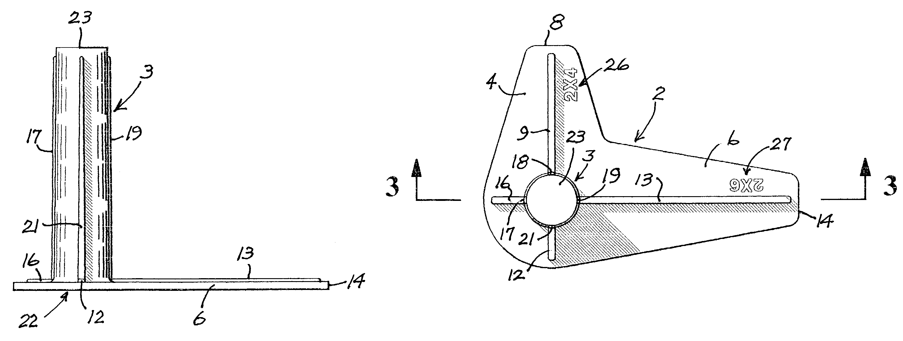
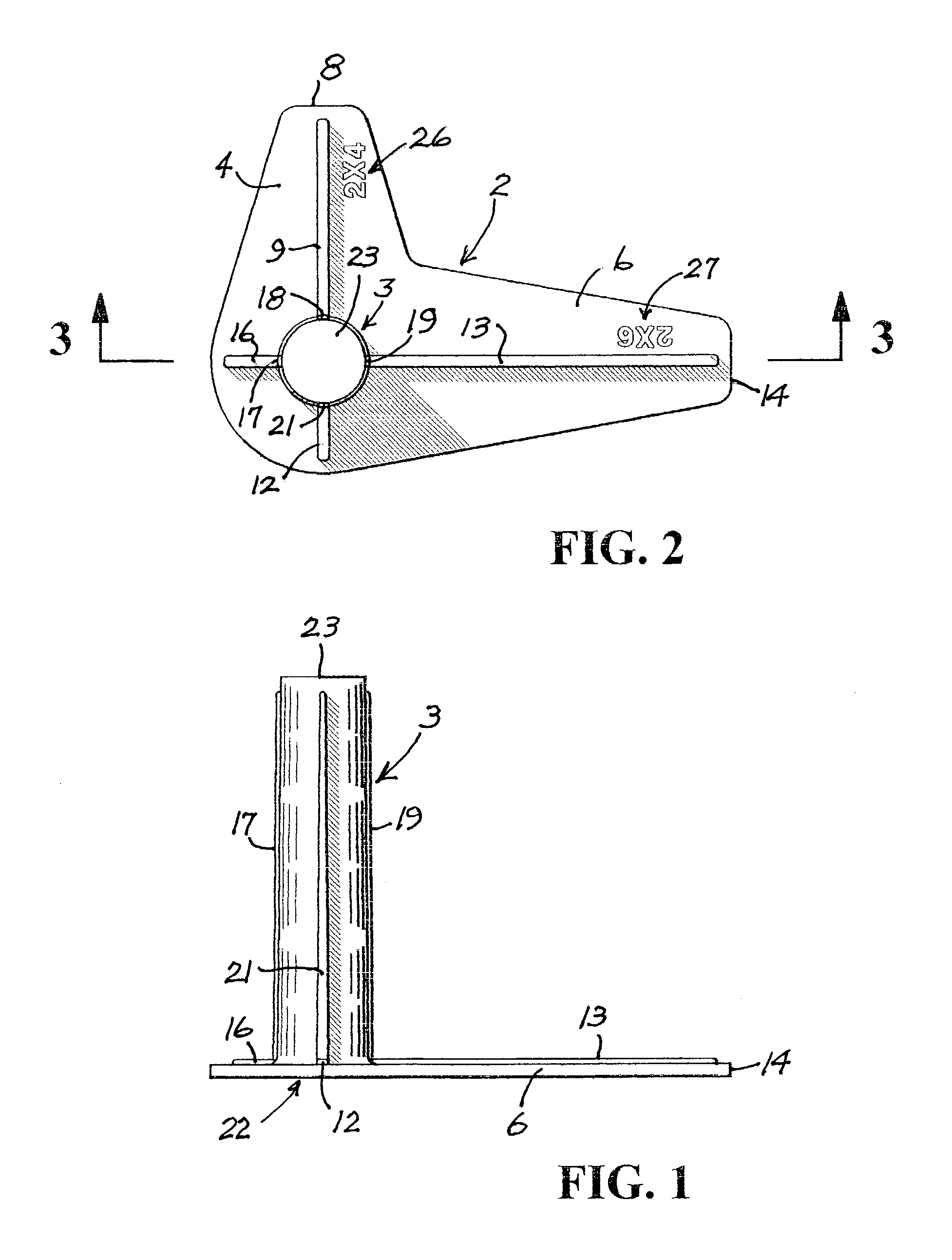
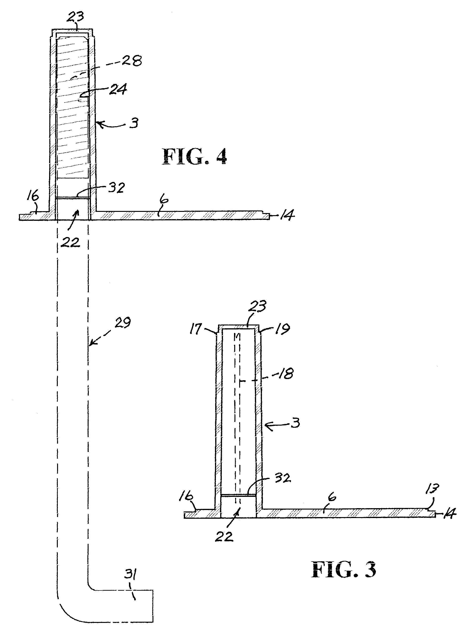
[0032]Referring to FIGS. 1 through 12 that embody and illustrate the anchor bolt positioning or placement device of the invention, it is noted that this embodiment is a pre-manufactured unitary or monolithic device injection molded from an appropriate synthetic resinous material that is tough and impact resistant, such as a phenolic, and is formed to provide a flat base portion designated generally by the numeral 2 and an integral vertically extending generally tubular projection integral with the base member and designated generally by the numeral 3. As seen in FIG. 2, the base member includes two laterally extending integral plate portions 4 and 6 extending at right angles to each other. The center lines of the two plate portions, if extended, would cross coincident with the central axis of the tubular projection 3. The extension 4 is utilized to measure the distance from the inner face of the form board or the outer face of the concrete foundation wall or the outside edge of a co...

second embodiment

[0038]From FIGS. 13 and 14, it will be seen that in this second embodiment of the invention the anchor bolt placement device is again provided with a vertically extending tubular member designated generally by the numeral 41, having the same configuration as the tubular projection 3 illustrated in FIG. 4, including the an open bottom end 22, a closed or otherwise terminated end 23, the reinforcing ribs previously mentioned and the radially inwardly projecting annular rib 32 adjacent the open end 22. This embodiment of the invention differs from the embodiment illustrated in FIGS. 1 through 5 in that the measurement means for determining the proper position of the anchor bolt for 2″×4″ and 2″×6″ mud sills are incorporated in a single laterally projecting elongated plate designated generally by the numeral 42. This is in distinction to the two lateral extensions 4 and 6 spaced 90° apart as illustrated in FIG. 1. Referring to FIG. 13, it will be seen that the single lateral extension p...

third embodiment

[0039]Referring to the invention illustrated in FIGS. 15, 15A and 16, it will be seen that in this embodiment of the invention the lateral extension constitutes an elongated base plate designated generally by the numeral 51 integral with the upwardly projecting tubular member 52 the structure of which is the same as the upwardly projecting tubular member 3 illustrated in FIG. 14. In this embodiment, the elongated base member 51 projects to the right of the upwardly projecting member 52 as seen in FIGS. 15 and 16 in a base portion designated generally by the numeral 53, this portion of the base having a central reinforcing rib 54 that extends medianly of the base to adjacent the end edge 56 of the elongated base member portion 53. Positioned on the top surface 57 of the base member portion 53 are laterally spaced transversely extending position-indicator ribs 58, 59, 61 and 62, each of these ribs being spaced apart one from the other approximately one inch. Note also that between the...


PUM


Abstract

Presented is an anchor bolt placement and protection device to facilitate setting of anchor bolts in concrete to facilitate placement of a mud sill. It is important that the anchor bolts that secure a mud sill to a foundation be properly spaced from the outside edge of the foundation. In one embodiment there is provided a device having a tubular projection open at one end to receive the threaded end of an anchor bolt. Projecting integrally from the bottom open end of the tubular projection are two lateral projections. One is adapted to place an anchor bolt when a 2×4 mud sill is used. The second projection positions the anchor bolt at the proper distance to receive a 2×6 mud sill. A second embodiment is provided with a single lateral projection extending perpendicularly from the open bottom end of the tubular projection. The top surface of the lateral extension is provided with cross-ribs and indicia that indicate the proper placement of either a 2×4 or 2×6 mud sill. A third embodiment provides a second laterally extending plate member in alignment with the first but on the opposite side of the tubular projection. Both extensions are provided with transverse ribs indicating the proper location of the device in relation to the underlying form boards.

Description

BACKGROUND OF THE INVENTION[0001]This invention relates broadly to concrete foundations and the foundation form boards between which the concrete is poured, and more particularly relates to mud sill anchor bolts and structural hardware bolts that are embedded in the concrete and to an anchor bolt placement device adapted to be detachably mounted on the threaded end of the anchor bolt and which functions to shield the threads from being coated with concrete during the pour and to properly position the anchor bolt in relation to the form boards between which concrete is poured.DESCRIPTION OF THE PRIOR ART[0002]It is well known that concrete is poured between concrete form boards that are usually set into trenches that accommodate the wooden forms which retain the concrete while it hardens. It has been the practice in industry to place a wooden spacer bar between the form boards at the bottom of the trench and to nail a cleat across the top edges of the form boards to retain the proper...

Claims


Application Information

Patent Timeline
Patent Type & Authority Patents(United States)
IPC IPC(8): E02D7/00E04H12/00
CPCE02D27/02
Inventor SMITH, JAMES R.
Owner SMITH JAMES R
Why Eureka
Try Eureka