Composition pulse time-of-flight mass flow sensor

a mass flow sensor and time-of-flight technology, applied in the direction of volume/mass flow by electromagnetic flowmeters, measurement devices, instruments, etc., can solve the problems of poor signal-to-noise at small flow rate, capable of operating at pressures as high as 2,000 psi, etc., and achieve rapid transport of ions and high reynolds number

Inactive Publication Date: 2007-06-05
SANDIA NAT LAB
View PDF2 Cites 58 Cited by
  • Summary
  • Abstract
  • Description
  • Claims
  • Application Information

AI Technical Summary

Benefits of technology

[0007]In contrast to prior art thermal flow sensors, the present invention is thermally robust in that no insulation is required to avoid thermal transients and it retains superior sensitivity as it is scaled down to the nanoliter flow rate regime and sub-millimeter dimension. Decreasing the scale of thermal flow sensors increases the heat transfer rate from the heated fluid volume to the surroundings due to a high surface-to-volume ratio and small length scale. This results in poor signal-to-noise at small flow rates (≈nL / min). In contrast, a composition pulse, such as produced here, retains its signal-to-noise ratio because mass diffusion is confined to the fluid and mass diffusivity is much smaller than thermal diffusivity. Moreover, this device is capable of operating at pressures as great as 2,000 psi, limited only by the strength of the materials of construction.
[0016]It can be advantageous to incorporate a flight tube into the flow channel as part of the detector means. The flight tube is concentric with flow channel and adjoined to the fluid exit of the flow channel and preferably smaller in diameter than the flow channel in order to achieve a high Reynolds number for rapid transport of the ions to the bulk flow. As will be appreciated by those skilled in the art, the dimensions of the flight tube can be selected for a particular flowrate range, fluid viscosity, and ion diffusivity to govern mass transport and hence, the response time and sensitivity of detection of the pulse produced by the upstream electrodes.

Problems solved by technology

This results in poor signal-to-noise at small flow rates (≈nL / min).
Moreover, this device is capable of operating at pressures as great as 2,000 psi, limited only by the strength of the materials of construction.

Method used


Image

  • Composition pulse time-of-flight mass flow sensor
  • Composition pulse time-of-flight mass flow sensor
  • Composition pulse time-of-flight mass flow sensor

Examples


Embodiment Construction

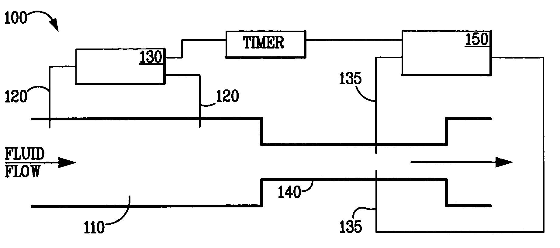
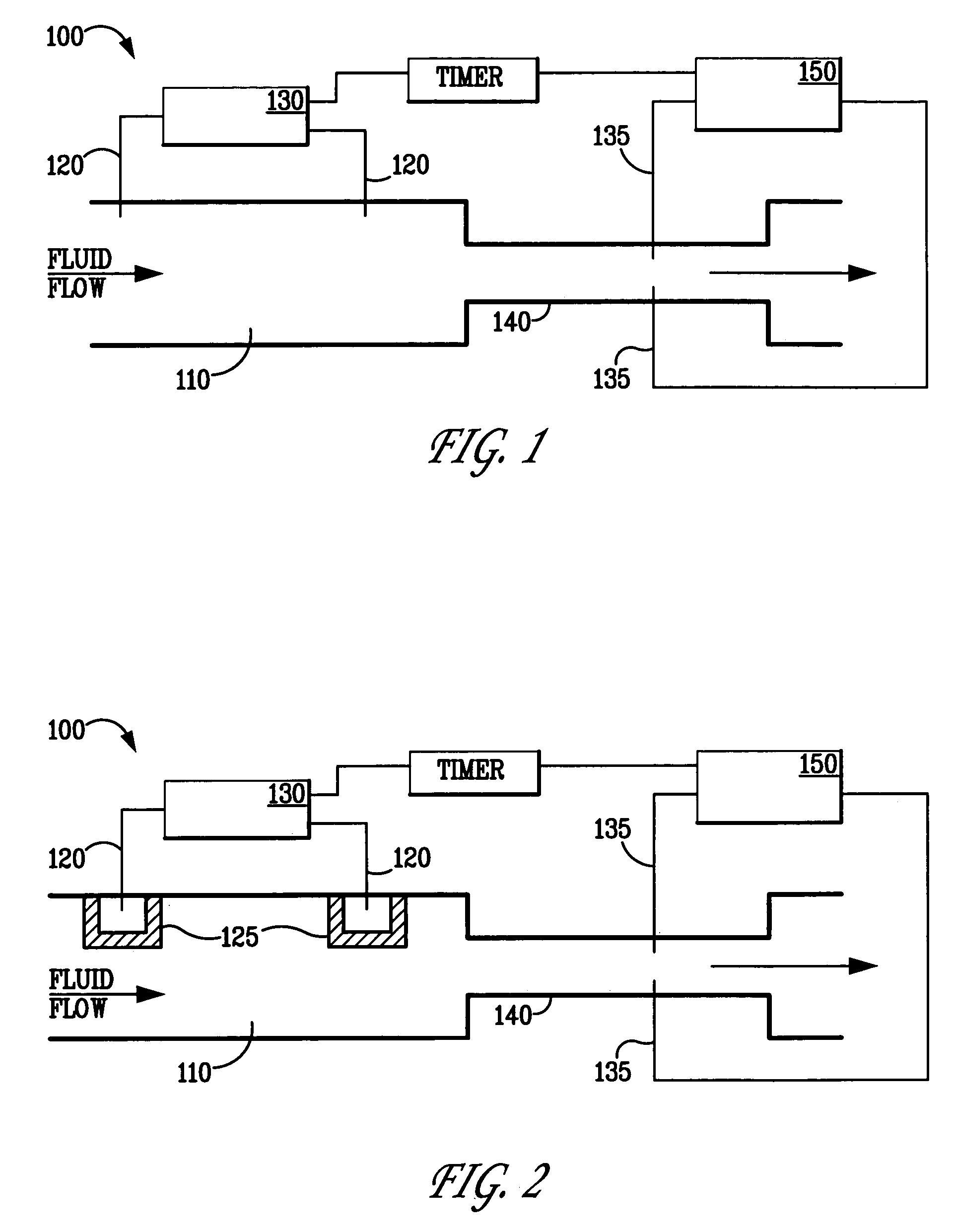
[0038]An embodiment of the invention and its operation are illustrated schematically in FIG. 1. Flow sensor 100 comprises a flow channel 110 having a single fluid entrance and a single exit where fluid flow is from left to right. A pair of spaced-apart electrodes 120 for producing an electrochemical pulse, or pair of pulses, one on each electrode, and consequent variation in composition of the fluid, including changes in the concentration of some component in the fluid, is disposed within the flow channel and along the flow axis. Means for supplying a voltage pulse to the electrodes, such as power supply 130, is connected to the electrodes. A flight tube 140 that is concentric with flow channel 110 can be adjoined to the fluid exit of the flow channel. As will be appreciated by those skilled in the art, the dimensions of the flight tube can be selected for a particular flowrate range and fluid properties such as viscosity and ionic diffusivity to govern mass transport and hence, the...


PUM


Abstract

A device for measuring fluid flow rates over a wide range of flow rates (<1 nL / min to >10 μL / min) and at pressures at least as great as 2,000 psi. The invention is particularly adapted for use in microfluidic systems. The device operates by producing compositional variations in the fluid, or pulses, that are subsequently detected downstream from the point of creation to derive a flow rate. Each pulse, comprising a small fluid volume, whose composition is different from the mean composition of the fluid, can be created by electrochemical means, such as by electrolysis of a solvent, electrolysis of a dissolved species, or electrodialysis of a dissolved ionic species. Measurements of the conductivity of the fluid can be used to detect the arrival time of the pulses, from which the fluid flow rate can be determined. A pair of spaced apart electrodes can be used to produce the electrochemical pulse. In those instances where it is desired to measure a wide range of fluid flow rates a three electrode configuration in which the electrodes are spaced at unequal distances has been found to be desirable.

Description

CROSS-REFERENCE TO RELATED APPLICATIONS[0001]This application is a Continuation-in-Part of prior application Ser. No. 10 / 210,647, filed Jul. 31, 2002, now U.S. Pat. No. 6,675,660.STATEMENT OF GOVERNMENT INTEREST[0002]This invention was made with Government support under contract no. DE-AC04-94AL85000 awarded by the U.S. Department of Energy to Sandia Corporation. The Government has certain rights in the invention.FIELD OF THE INVENTION[0003]The present invention relates generally to a device, capable of operating at high pressure, for the detection of fluid flow rates over a wide range of flow rates (<1 nL / min to >10 μL / min) and particularly for measuring fluid flow rates in microfluidic devices.BACKGROUND OF THE INVENTION[0004]Numerous types of mass flow meters are generally available. Some are based on viscous drag, others employ the Venturi effect to measure a pressure drop, still others use positive displacement either rotary or linear. For low flow rates, local heating of...

Claims


Application Information

Patent Timeline
Patent Type & Authority Patents(United States)
IPC IPC(8): G01F1/58G01F1/7088
CPCG01F1/7088
Inventor HARNETT, CINDY K.CROCKER, ROBERT W.MOSIER, BRUCE P.CATON, PAMELA F.STAMPS, JAMES F.
Owner SANDIA NAT LAB
Why Eureka
Try Eureka