Clamp lock brush seal assembly

a brush seal and clamp lock technology, applied in the direction of engine seals, leakage prevention, machines/engines, etc., can solve the problems of time-consuming and expensive heat treatment process, high cost of brush seal bristle packs, and high cost of replacing the entire brush seal, so as to save costs, easy to disassemble and repair, and easy to disassemble

Active Publication Date: 2007-06-05
RTX CORP
View PDF39 Cites 17 Cited by
  • Summary
  • Abstract
  • Description
  • Claims
  • Application Information

AI Technical Summary

Benefits of technology

[0011]The support is provided with a location which allows for adequate clearance of a retention lip on the retaining ring to allow for radial installation of the retaining ring. Clamping bolts are used to ensure uniform clamping forces. The sideplate of the brush seal can contain recessed holes or turned diameter to accept the clamping bolts. Because the seal can be readily disassembled, it is an advantageous configuration for test engines and rigs. The design makes it easy to test various brush materials, wire sizes, bore sizes, etc. which results in a significant cost savings. The brush seal design of the present invention can be readily disassembled and repaired in the field with a minimum of tools. In addition, seals using non-weldable plate materials can benefit from this configuration.

Problems solved by technology

The heat treatment process is time consuming and can be expensive.
This means a mechanic must replace the entire brush seal during maintenance.
The bristle packs of the brush seal are expensive.
The main factor influencing cost is the amount of raw material used.

Method used


Image

  • Clamp lock brush seal assembly
  • Clamp lock brush seal assembly
  • Clamp lock brush seal assembly

Examples


Embodiment Construction

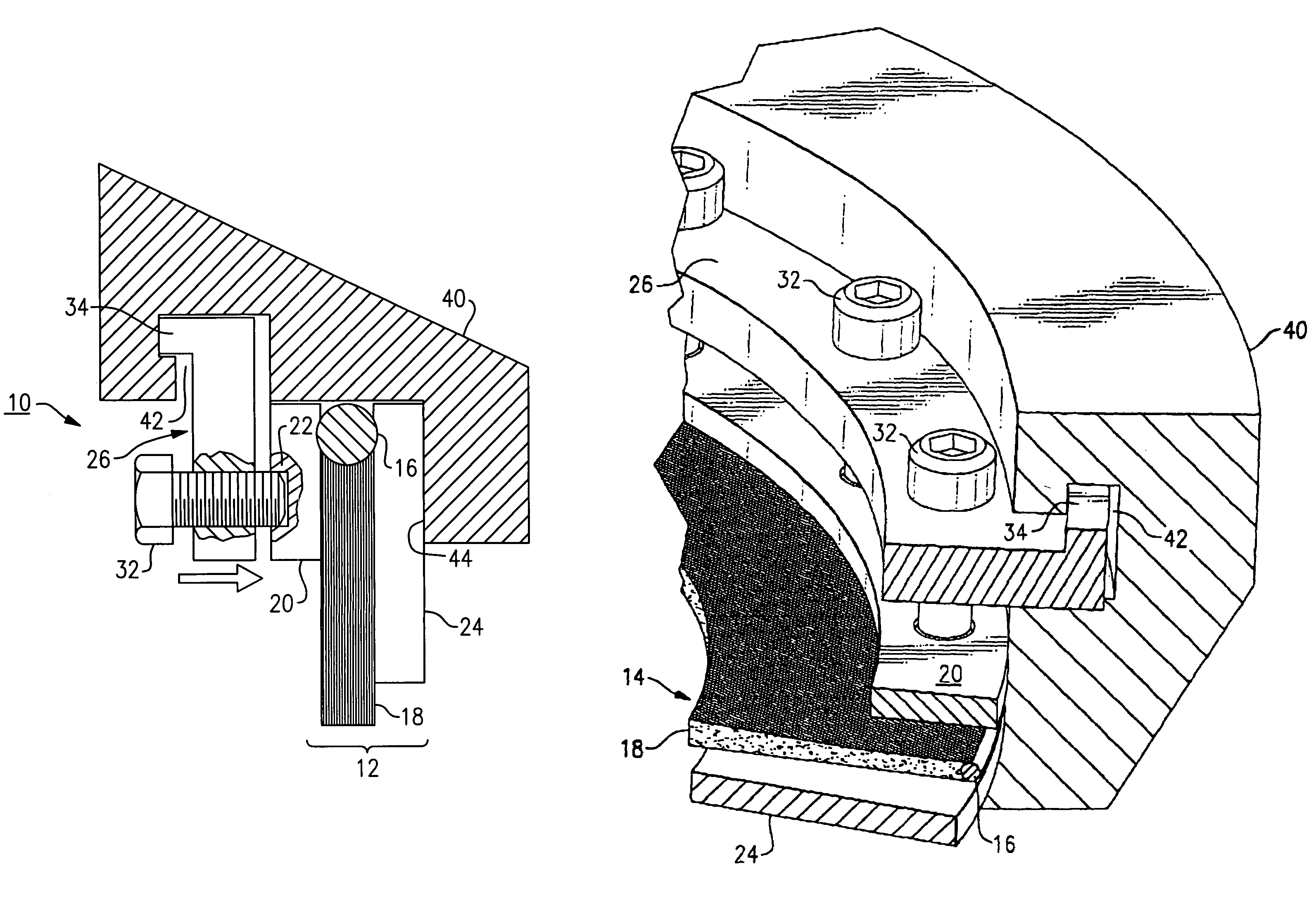
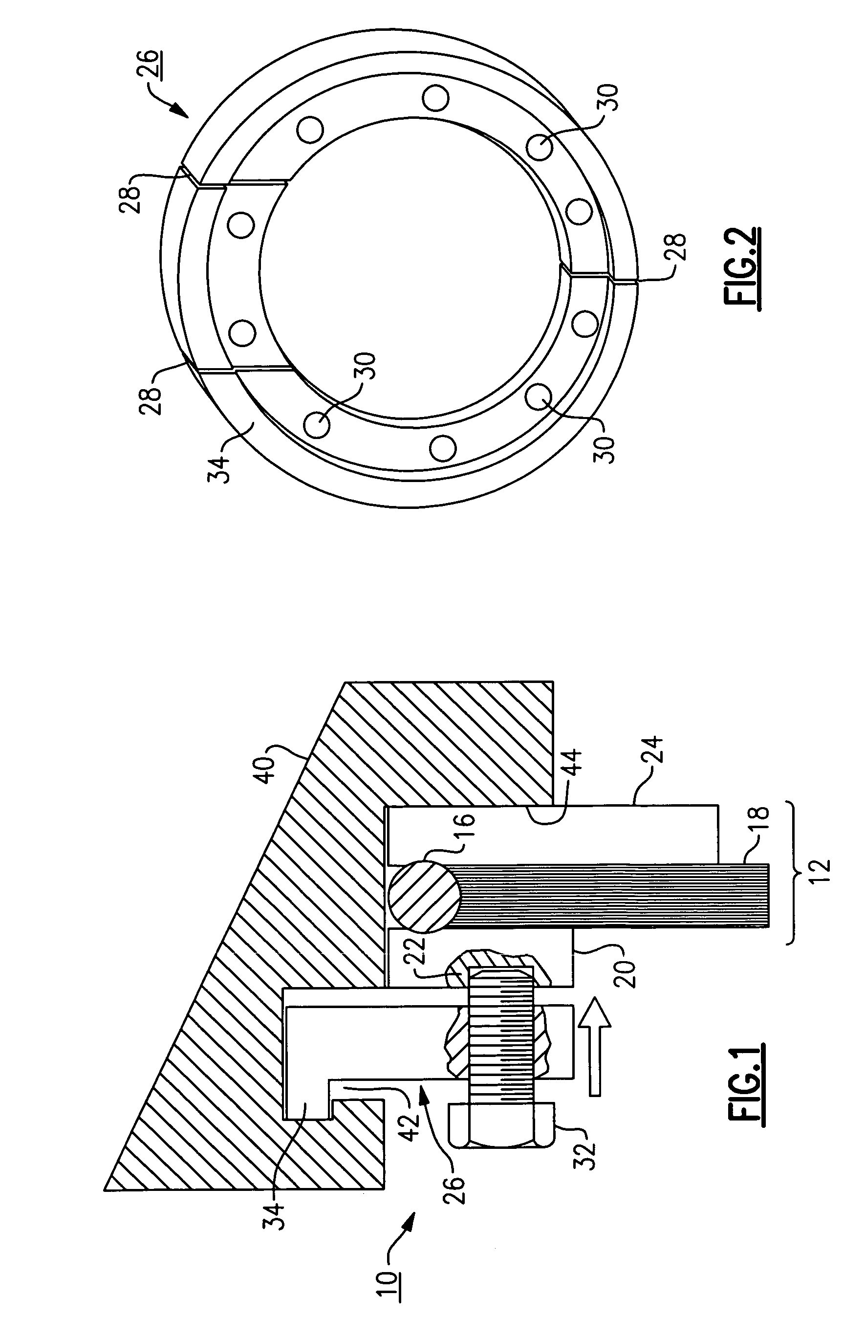
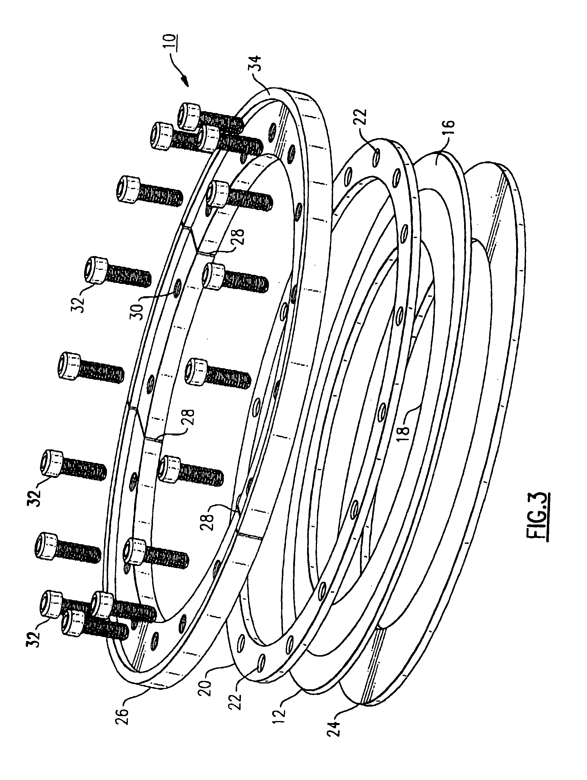
[0021]FIG. 1 illustrates one embodiment of a brush seal assembly 10 of the present invention held in a support member or housing 40. The brush seal assembly 10 is made up of a brush seal 12 and a segmented or split clamping retaining ring 26.

[0022]The brush seal 12 includes a welded bristle hoop 14 having a weld 16 which holds a plurality of bristles in the form of a bristle pack 18 in place. A side plate 20 and backplate 24 sandwich the bristle hoop. The two plates and bristle hoop are loose and not welded together. The following United States Patent Application Publications: US 2003 / 0160392 A1; US 2003 / 017878A1 and US 2003 / 017877A1, herein incorporated by reference, describe the manufacture and assembly of such a brush seal in greater detail. The plates 20, 24 and bristle pack 18 are positioned as shown in FIG. 1 against a backface 44 of support member 40 and held in place by the clamping force of retention ring 26. More specifically the retaining ring 26 is split or segmented at ...


PUM


Abstract

A brush seal assembly which includes a brush seal which is bristle hoop positioned between two plates. A segmented ring is positioned in contact with the brush seal and provides a uniform clamping force against the seal to hold it in place within a support member.

Description

FIELD OF THE INVENTION[0001]This invention relates generally to brush seals and more specifically to a brush seal assembly.BACKGROUND OF THE INVENTION[0002]Brush seals are commonly used on various applications, including gas turbine engines. The brush seal is typically used to prevent secondary flow in the engine from escaping through a gap between a stationary part such as a diffuser case and a rotating part (e.g. a turbine shaft). Brush seals may also have other uses, such as sealing a gap between stationary parts of the engine.[0003]A brush seal typically includes packs of wire bristles sandwiched between plates. The bristle packs and plates are typically welded together to form the brush seal. The brush seal must undergo heat treatment after the welding step to relieve any residual stresses. Heat treatment typically involves securing the brush seal within a fixture, then placing the fixture in an oven. The heat treatment process is time consuming and can be expensive.[0004]The w...

Claims


Application Information

Patent Timeline
Patent Type & Authority Patents(United States)
IPC IPC(8): F01D11/02F16J15/44
CPCF16J15/3288
Inventor ADDIS, MARK E.
Owner RTX CORP
Why Eureka
Try Eureka