Audio lanyard

a technology of audio lanyards and lanyards, which is applied in the direction of optics, lens assemblies, instruments, etc., can solve the problems of affecting the appearance of the eyewear, the weight of the electronics and speakers is borne, and the electronics and speakers may be damaged, etc., to achieve the effect of reducing the burden of supporting the conventional eyewear, reducing the burden of supporting the eyewear, and ensuring the stability of the eyewear

Inactive Publication Date: 2007-06-05
DAKA RESEARCH INC
View PDF3 Cites 25 Cited by
  • Summary
  • Abstract
  • Description
  • Claims
  • Application Information

AI Technical Summary

Benefits of technology

[0009]An audio lanyard audio device provides a number of advantages not seen with earlier devices. First, the audio lanyard has a pair of soft openings to accept the ear pieces of conventional eyewear in a manner that supports and engages several inches of the ear pieces of conventional eyewear with sufficient surface area and friction to hold the conventional eyewear securely. Second, the audio lanyard, by engaging a significant length of the conventional eyewear, provides a length of softer foam material for fitting both the lanyard and convention eyewear ear pieces between the ear and head in a more body shape accommodating manner, in essence padding the conventional eyewear ear pieces against the ear and head.
[0010]Third, the audio lanyard forms a balanced combination when worn with conventional eyewear. The rear part of the lanyard contains all of the electronics necessary for operation, and helps counterbalance the conventional eyewear. Although the audio lanyard is flexible, it has a shape meant to fit around the rear of the human head and helps lighten the burden of supporting the conventional eyewear. This counterbalancing, combined with the lack of excess length, enables the audio lanyard and conventional eyewear combination to be worn in a more secure, balanced and stable manner.
[0012]Because the audio lanyard can further isolate an external battery acceptance cavity from the internal electronics, the moisture from either the environment or sweat cannot enter and degrade the electronics. A much wider array of controllability and programmability is achievable by providing programmability and downloadability either through an infrared or electromagnetic port. As with other devices, battery rechargability can be had with electrical connection or electromagnetic induction.

Problems solved by technology

There are several disadvantages from this design.
The first is the bulkiness of locating the electronics in housings outside the ears.
Further, where the audio appliance is used during sports activities, the bulky, outboard electronics and speakers may be damaged from racquet balls, tennis balls, or from the arms and hands of the user.
A second problem is that for “headphone style” designs, the bulk of the weight of the electronics and speakers are borne by a strap or other support (typically adjustable) over the head.
Where the design depends solely upon the ears for vertical support, the outer ears bear the total vertical support for the weight of the device, making it uncomfortable to wear the device for long periods.
A third problem, especially for eyeglass wearers, is the competition for the area between the upper external ear and skull.
Where the audio appliance is “headphone like” and presses the ears inward, skin bruising or painful compression can occur.
If both structures are present, the ears are bent outward and the need for downward support from the ear is compromised.
If the structures are stacked and the conventional eyewear support is on top, the eyewear is tilted and does not fit properly.
If the structures are stacked such that the conventional eyewear support is on bottom, the audio appliance may not fit properly or may move to the outside of the eyewear and worsen the discomfort to the user.
In terms of conventional eyewear alone, most lanyard devices can cause discomfort.
A lanyard attached near the distal ends of the ear pieces is much more likely to form an unwanted irritation for the user.
Further, where a loop lanyard is attached to an area at the distal-most area of the conventional eyewear supports, it may likely fail to prevent the eyewear from striking the ground as the lanyard attachment loop may become weak and / or slip to the point of disengagement.
Further, conventional lanyards can be distracting.
The user can see forward mounted lanyards move when the head moves, and rearwardly connected lanyards can bunch and tangle near the collar to cause an annoyance for the user.
Where the user is not wearing a collar, a lanyard trailing from conventional eyewear can cause further annoyance.
This minimalist structure is typically cheap, intended only to provide minimal restraint should the eyewear become dislodged, and does little to increase the user's comfort.
In cases where the eyewear is heavy and becomes dislodged from the user's head frequently, the lanyard may fail or damage may still result in damage where the eyewear can strike a table top.
Further, most conventional lanyards do nothing to increase the user's comfort.

Method used


Image

  • Audio lanyard
  • Audio lanyard
  • Audio lanyard

Examples


Embodiment Construction

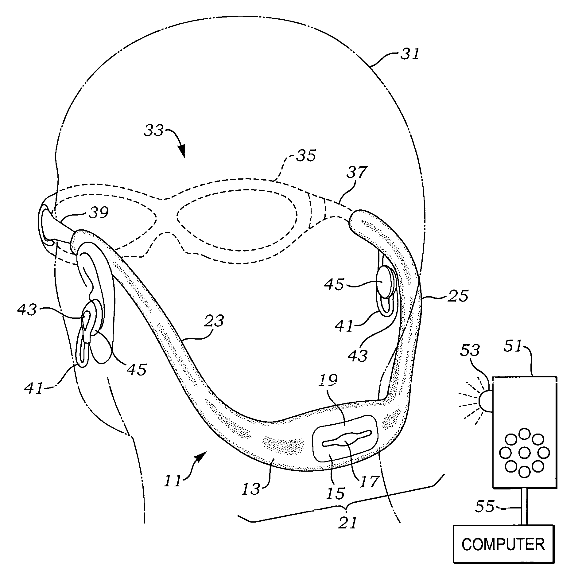
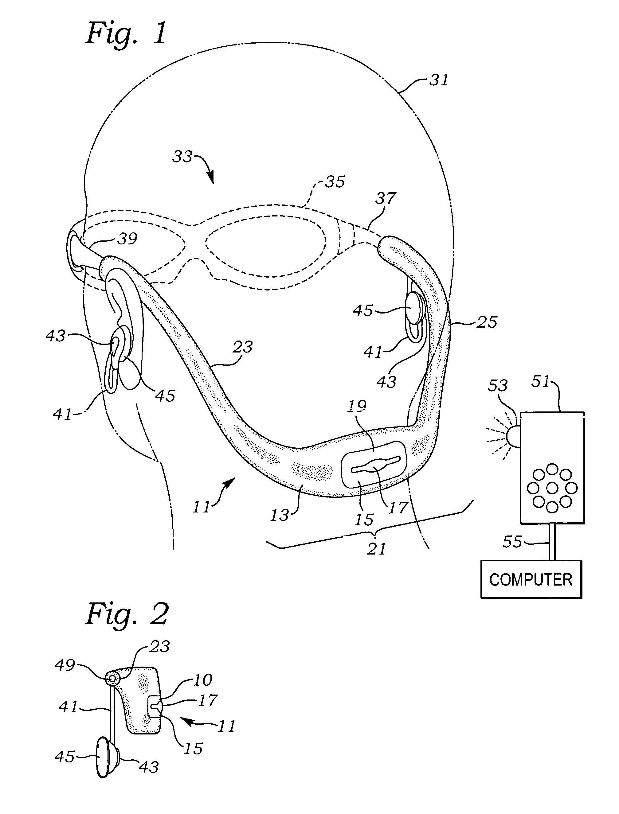
[0019]An audio lanyard 11 includes a main continuous housing 13 having a control area 15 which is shown as including a raised manual touch bar 17. Other structures could be used to manually register the user to the specific controls of the control areas 15, including raised buttons structures, triangular structures and the like. For example, where the audio lanyard 11 is a radio, the manual touch bar 17 could have its middle area indicate a change in station, while the outer area to either side indicate up and down volumes. Where the audio lanyard 11 is a mp3 player, the manual touch bar 17 could have its middle area indicate a change in music selection, while the outer area to either side indicate up and down volumes. Other more specific controls are possible.

[0020]A light emitting diode (LED) port 19 is a possible structure which can be used to indicate an on or off condition, as well as to be used to perform infrared file transfers and programming information data. Other light po...


PUM


Abstract

An audio lanyard audio device provides a number of advantages not seen with earlier devices, including, (1) a pair of soft openings to accept the ear pieces of conventional eyewear in a manner that supports and engages several inches of the ear pieces of conventional eyewear with sufficient surface area and friction to hold the conventional eyewear securely, (2) provision of a length of softer foam material for fitting both the lanyard and convention eyewear ear pieces between the ear and head, (3) formation of a balanced combination when worn with conventional eyewear, and (4) the location of the controls and main electronics and battery at the rear for balance and easy reach by a user.

Description

FIELD OF THE INVENTION[0001]The present invention relates to personal listening equipment and appliances and more particularly to an integrated audio lanyard which can be utilized with conventional eyewear having ear supports, which has a more water tight design, and which can be used as a conventional eyeglass lanyard.BACKGROUND OF THE INVENTION[0002]A number of personal audio systems have been developed for use by active persons. One of the best examples is an audio headset having two ends joined by a flexible support. The electronics for operation are located adjacent the ends of the flexible support, which typically extend to and perhaps may derive support from the user's ears. The flexible support may be worn in positions ranging from an upper position across the users skull, to a rearward position across the back of a user's head.[0003]There are several disadvantages from this design. The first is the bulkiness of locating the electronics in housings outside the ears. Typicall...

Claims


Application Information

Patent Timeline
Patent Type & Authority Patents(United States)
IPC IPC(8): G02C1/00
CPCG02C11/10
Inventor MAH, PAT Y.
Owner DAKA RESEARCH INC
Why Eureka
Try Eureka