Storage system

a storage system and disk drive technology, applied in the field of storage systems, can solve the problems that the drives located at the lower tiers, some distance from the cooling fan, cannot be sufficiently cooled, etc., and achieve the effects of high cooling performance, high disk drive packaging density, and good maintainability and serviceability

Active Publication Date: 2007-06-05
RAKUTEN GRP INC
View PDF6 Cites 62 Cited by
  • Summary
  • Abstract
  • Description
  • Claims
  • Application Information

AI Technical Summary

Benefits of technology

[0008]An advantage of some aspects of the invention is to provide a storage system including multiple disk drives that offers high disk drive packaging density, good maintainability and serviceability and high cooling performance.
[0010]According to the storage system pertaining to the first aspect, because the multiple racks are arranged to form a substantially polygonal cylinder-shaped central space used for maintenance work, a high packaging density can be obtained while preserving an area to be used for maintenance work. Furthermore, because the cooling devices are arranged to form a second surface that is substantially parallel to the disk drives arranged to form a first surface in each of the multiple racks, cooling performance can be improved.
[0012]According to the storage system pertaining to the second aspect, because the multiple racks are arranged to form a substantially polygonal cylinder-shaped central space used to enable maintenance work to be carried out, a high packaging density may be obtained while preserving an area to be used for maintenance work. Furthermore, because the first and second disk drives are arranged to form the inner surfaces and outer surfaces of the racks, and the cooling devices are arranged to form surfaces of the doors that face the inner or outer surfaces in a substantially parallel fashion when closed, disk drive cooling performance is increased. Moreover, because the doors are mounted so as to be openable and closable, the worker can easily perform maintenance work even to disk drives that are arranged to form the surface of the side on which the doors are mounted.

Problems solved by technology

As a result, there is a danger that the drives at the lower tiers that are located some distance from the cooling fan cannot be sufficiently cooled.

Method used


Image

  • Storage system
  • Storage system
  • Storage system

Examples


first embodiment

A. First Embodiment

[0033]A-1. Construction of Storage System

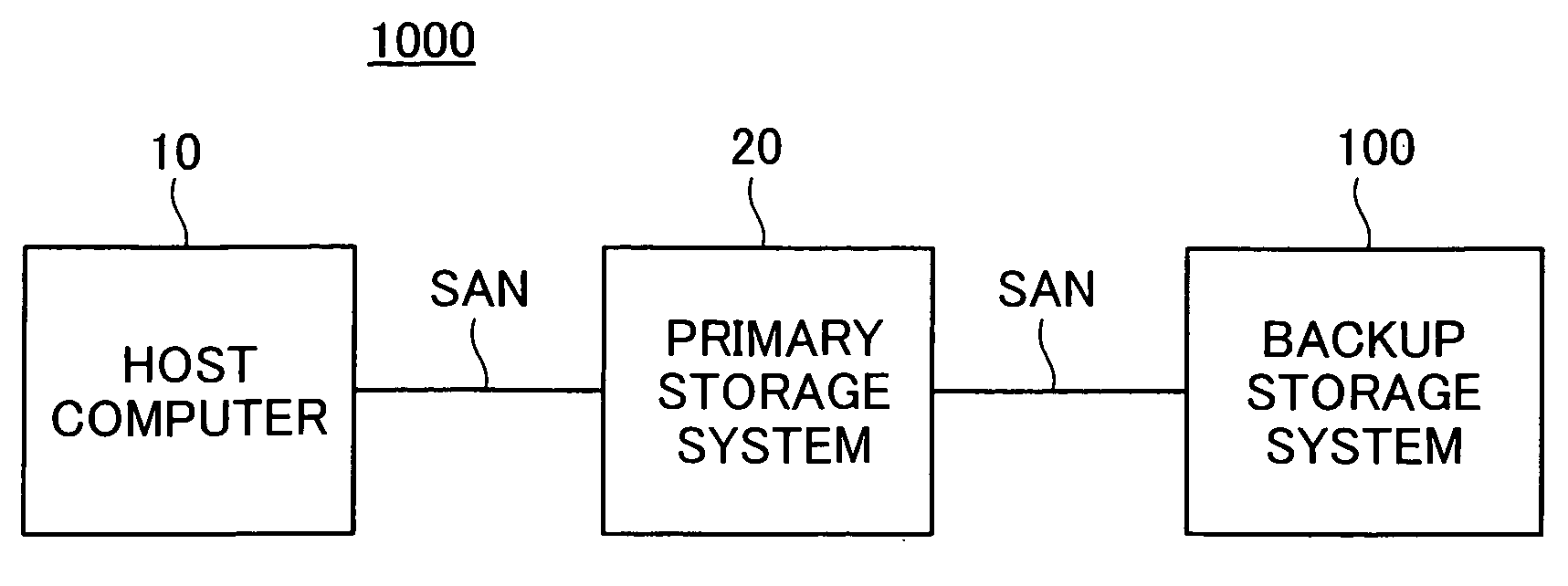
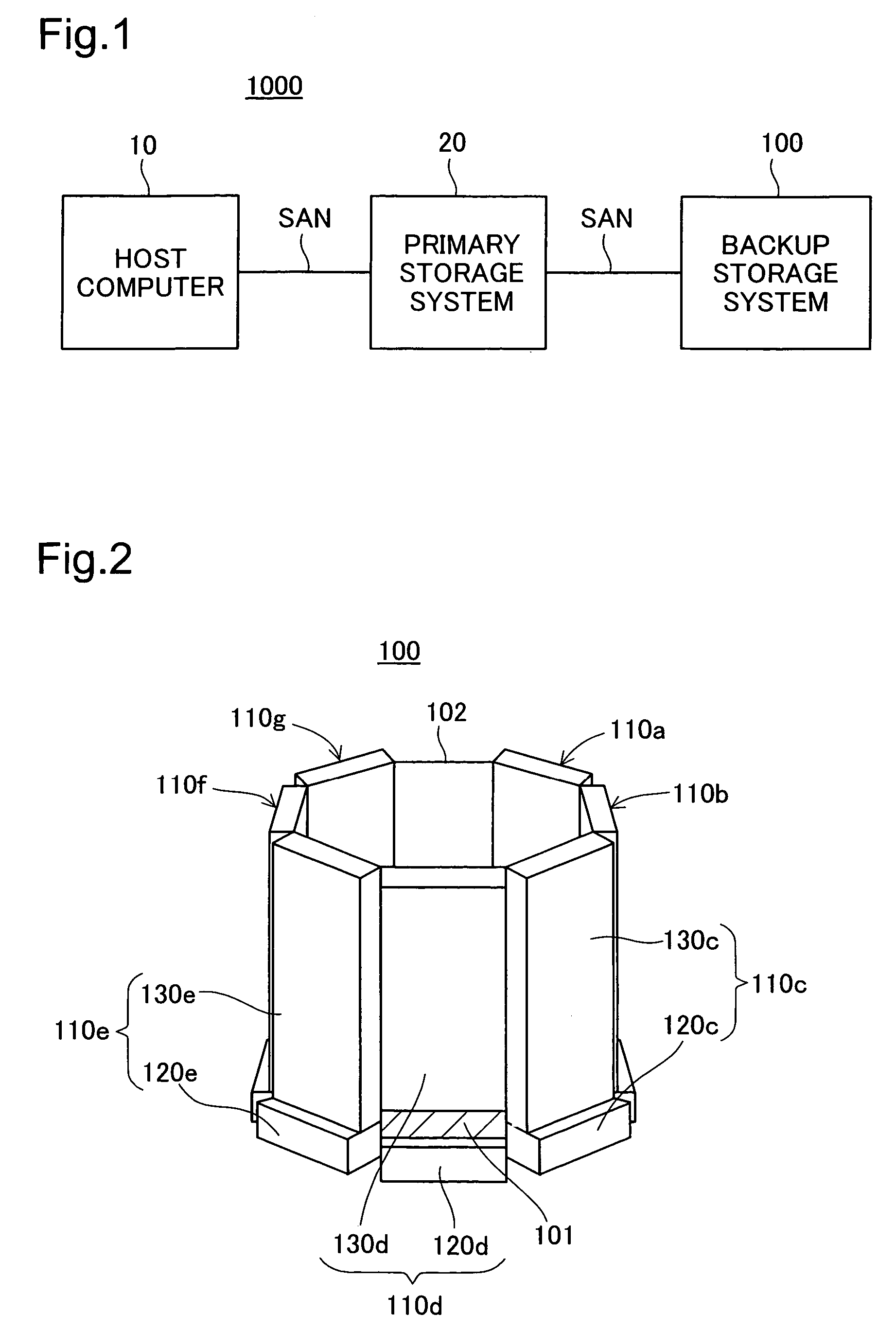
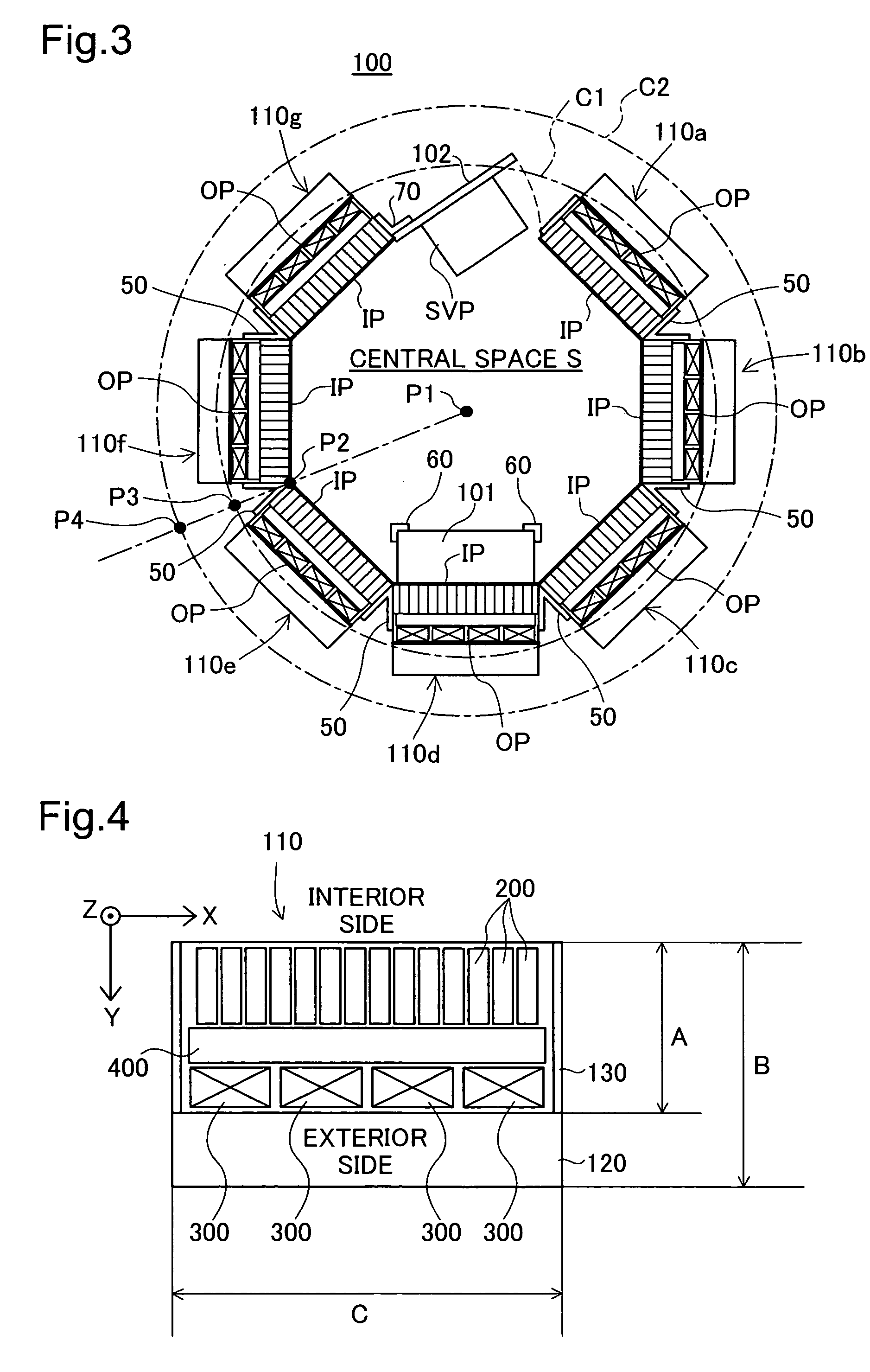
[0034]The basic construction of the storage system pertaining to a first embodiment will now be described with reference to FIGS. 1–3. FIG. 1 shows a schematic of one example of the arrangement of a computer system including the storage system pertaining to a first embodiment. FIG. 2 shows a perspective view of the external appearance of the storage system pertaining to the first embodiment. FIG. 3 shows a cross-sectional view of the storage system pertaining to the first embodiment cut along a plane parallel to the installation surface.

[0035]The computer system 1000 shown in FIG. 1 includes a host computer 10, a primary storage system 20 and a backup storage system 100. The host computer 10 and primary storage system 20 are communicably connected over a SAN (Storage Area Network). Similarly, the primary storage system 20 and the backup storage system 100 are communicably connected over a SAN. The host computer 10 uses the ...

second embodiment

B. Second Embodiment

[0062]A storage system pertaining to a second embodiment will now be described with reference to FIGS. 11–13. FIG. 11 shows a cross-sectional view of a storage system pertaining to the second embodiment cut along a plane parallel to the installation surface. FIG. 12 shows an external perspective view of the storage system pertaining to the second embodiment. FIG. 13 shows a block diagram of a functional construction to control ceiling fans. In the storage system 100A pertaining to the second embodiment, a construction opposite that used in the storage system 100 pertaining to the first embodiment is employed, i.e., in each enclosure 135 of a given rack 110, the cooling fans 300 are arranged on the interior side of the wiring board 400 and the disk drives 200 are arranged on the exterior side thereof. As a result, the disk drives 200 form a part of the outer surface OP of the rack 110, while the cooling fans 300 form a part of the inner surface IP of the rack 110....

third embodiment

C. Third Embodiment

[0068]A storage system pertaining to a third embodiment will now be described with reference to FIGS. 14–17. FIG. 14 shows a cross-sectional view of the storage system pertaining to a third embodiment cut along a plane parallel to the installation surface. FIG. 15 shows a side view of a door seen from a perspective facing a rack 110. FIG. 16 shows a first perspective view of the exterior of the storage system pertaining to the third embodiment. FIG. 17 shows a second perspective view of the exterior of the storage system pertaining to the third embodiment.

[0069]In the storage system 100B pertaining to the third embodiment, first disk drives 201 are arranged on the interior side of the wiring board 400 in each rack 110, while second disk drives 202 are arranged on the exterior side of the wiring board 400. As a result, the first disk drives 201 form a part of the inner surface IP of the rack 110, while the second disk drives 202 form a part of the outer surface OP ...


PUM


Abstract

In a storage system that includes multiple disk drives, the disk drive packaging density is increased, and maintainability and serviceability, as well as cooling performance, are improved. The storage system includes multiple racks, multiple disk drives and multiple cooling devices. The multiple racks are arranged to form a substantially polygonal cylinder-shaped central space used to enable maintenance work to be carried out. Furthermore, an entrance area for a worker to enter the central space is formed between a first rack and a second rack among the multiple racks. The multiple disk drives are detachably mounted to one side of inside and outside of the multiple racks, and are arranged to form a first surface in each of the multiple racks. The multiple cooling devices are arranged to form a second surface in each of the multiple racks. The second surface is substantially parallel to the first surface.

Description

CROSS REFERENCE TO RELATED APPLICATIONS[0001]This application relates to and claims priority from Japanese Patent Application No.2005-275025, filed on Sep. 22, 2005, the entire disclosure of which is incorporated by reference.BACKGROUND[0002]1. Technical Field[0003]The present invention relates to a storage system, and more particularly to a storage system that includes multiple disk drives.[0004]2. Description of the Related Art[0005]Storage systems that include multiple disk drives are known in the art as secondary storage systems connected to one or more computers. In recent years, there has been a trend toward increasing the storage capacities of such storage systems by including a large number of disk drives. For example, one key type of storage system for storing large amounts of data uses so-called MAID (Massive Arrays of Idle Disks) technology. In a storage system that employs MAID technology, there may be approximately 1000 disk drives for each storage system, enabling the ...

Claims


Application Information

Patent Timeline
Patent Type & Authority Patents(United States)
IPC IPC(8): G06F1/16H05K7/00
CPCG06F1/181G06F1/20G11B15/6835
Inventor TANAKA, KATSUYASHIMADA, KENTARO
Owner RAKUTEN GRP INC
Why Eureka
Try Eureka