Application-specific object-based segmentation and recognition system

a recognition system and object-based technology, applied in the field of application-specific object-based segmentation and recognition system, can solve the problems of reducing compression ratio, high false alarm rate, and user not knowing if the alarm is a true false alarm

Inactive Publication Date: 2007-06-05
XLABS HLDG
View PDF5 Cites 495 Cited by
  • Summary
  • Abstract
  • Description
  • Claims
  • Application Information

AI Technical Summary

Benefits of technology

[0026]A video detection apparatus and method is disclosed which may be adapted to detect and follow movement of a predefined object of interest within the video data of the output of a video camera encoded in frame-wise data, each frame occurring at sequential the intervals, and including the segmentation of at least one portion of the frame-wise data, an object segment, as potentially including the preselected object of interest, and including vertical edge pixels and horizontal edge pixels detected to be present within the object segment, and may comprise: an edge symmetry detection unit which may comprise: a vertical symmetry detector adapted to compute the vertical symmetry of at least one of the set of vertical edge pixels and the set of horizontal edge pixels in each column about a horizontal axis passing through the object segment, and to produce a vertical symmetry value for columns within the object segment; a horizontal symmetry detector adapted to compute the horizontal symmetry of at least one of the set of vertical edge pixels and set of horizontal edge pixels in each row about a vertical axis passing through the object segment, and to produce a horizontal symmetry value for rows within the object segment; and, an edge symmetry feature set computation apparatus adapted to compute an edge symmetry feature set for the object segment based upon the vertical symmetry values and the horizontal symmetry values; and, a background modeling unit which may comprise: a background modeling apparatus adapted to isolate from a current frame at least one segment of the current frame, each of the at least one segments containing a possible object of interest within the current frame, on a frame-wise basis, and to provide as an output each of the at least one segments; an object of interest classifying apparatus adapted to determine whether or not any segment of the at least one segments output from the background modeling apparatus includes a object of interest and to characterize any such segment as an object segment, utilizing at least in part the edge symmetry feature set; an object segment tracking apparatus adapted to track the location within the current frame of any object segment, and to determine a projected location of the object segment in a subsequent frame, and to provide the background modeling apparatus with the projected location in the subsequent frame of the object segment; and wherein the background modeling apparatus is adapted to provide as its output the projected location of the object segment in the subsequent frame in lieu of a segment from the subsequent frame determined by the background modeling apparatus to contain a possible object of interest or in the event that the background modeling apparatus is unable in the subsequent frame to locate any segment containing a possible object of interest. The method and apparatus may computing the vertical symmetry and the horizontal symmetry of the set of vertical edge pixels and the set of horizontal edge pixels. The object segment tracking apparatus may further comprise: a matching apparatus adapted to match the location of an object segment in the current frame to one of a plurality of projected locations of the object segment in the current frame, which projections are based upon the location of the respective object segment in at least one prior frame; and, a track provider adapted to receive and store the location of an object segment in the current frame and over a plurality of prior frames and adapted to provide the projections of the location of the object segment in a subsequent frame based upon the locations of the object segments in the current frame and the plurality of prior frames. The vertical symmetry detector may be adapted to compute the vertical symmetry value of at least one of the set of horizontal edges or the set of vertical edges in a given column i as the ratio of the number of horizontal edge pixels or vertical edge pixels, respectively, in each column i on opposing sides of the horizontal axis, independent of which side has more horizontal edge pixels or vertical edge pixels, respectively, expressed as a number between 0, if there are no horizontal edge pixels or no vertical edge pixels, respectively, on either side of the horizontal axis and 1.0 if there are, respectively, an equal number of horizontal edge pixels or vertical edge pixels, respectively on both sides of the horizontal axis; and the horizontal symmetry detector may be adapted to compute the horizontal symmetry value of at least one of the set of horizontal edges or the set of vertical edges in a given row j as the ratio of the number of horizontal edge pixels or vertical edge pixels, respectively, in each row j on opposing sides of the vertical axis, independent of which side has more horizontal edge pixels or vertical edge pixels, respectively, expressed as a number between 0, if there are no horizontal edge pixels or no vertical edge pixels, respectively, on either side of the horizontal axis and 1.0 if there are, respectively, an equal number of horizontal edge pixels or vertical edge pixels, respectively on both sides of the vertical axis. The background modeling apparatus may be adapted to provide as its output the projected location of the object segment in the subsequent frame in order to override any conflict in the labeling of pixels in the subsequent frame as part of a segment containing a possible object of interest and the feature set computation apparatus may further comprise: a horizontal fuzzy set computation apparatus adapted to compute a fuzzy set value for each of a plurality of horizontal fuzzy sets each having a selected weighting function applicable to a selected group of columns within the object segment, with the columns grouped according to position along the horizontal axis in the object segment; and a vertical fuzzy set computation apparatus adapted to compute a fuzzy set value for each of a plurality of vertical fuzzy sets each having a selected weighting function applicable to a selected group of rows within the object segment, with the rows grouped according to position along the vertical axis in the object segment. The background modeling apparatus may be adapted to isolate from a current frame the at least one segment of the current frame utilizing the video object plane extracted from the current frame, and the horizontal fuzzy sets may further comprise: a left extreme fuzzy set having a weighting function that is a constant value for a first selected number of columns from the left border of the object segment toward the vertical axis of the object segment and decreases to zero over a second selected number of columns toward the vertical axis if the object segment; and, a right extreme fuzzy set having a weighting function that is a constant value for a third selected number of columns from the right border of the object segment toward the vertical axis of the object segment and decreases to zero over a fourth selected number of columns toward the vertical axis of the object segment; and at least one horizontal internal fuzzy set having a weighting function that increases from zero to a peak value and decreases to zero as the columns contained in each such internal fuzzy set go from left to right across the object image; and, the vertical fuzzy sets may further comprise: a bottom extreme fuzzy set having a weighting function that is a constant value for a fifth selected number of rows from the bottom border of the object segment toward the horizontal axis of the object segment and decreases to zero over a sixth selected number of rows toward the horizontal axis if the object segment; a top extreme fuzzy set having a weighting function that is a constant value for a seventh selected number of columns from the top border of the object segment toward the horizontal axis of the object segment and decreases to zero over an eighth selected number of rows toward the horizontal axis of the object segment; and, at least one vertical internal fuzzy set having a weighting function that increases from zero to a peak value and decreases to zero as the rows contained in each such vertical internal fuzzy set go from bottom to top across the object image. The at least one segment of the current frame may comprise a bounding box, and the columns associated with each of the horizontal fuzzy sets may be overlapping into respective adjacent horizontal fuzzy sets; and, the rows associated with each of the vertical fuzzy sets may be overlapping into respective adjacent vertical fuzzy sets. The feature set computation apparatus may further comprise a fuzzy set edge value score computing apparatus adapted to compute a fuzzy set edge value based upon the respective horizontal edge value or vertical edge value for the respective column or row and the respective horizontal fuzzy set weighting function value for the respective column or the respective vertical fuzzy set weighting function for the respective row.

Problems solved by technology

These sensors are often triggered by pets or wind, or the like, resulting in high false alarm rates.
In existing systems the video cameras will often not capture the source of an intruder alarm, leaving the user not knowing if the alarm is a true false alarm (and if it is, what caused it) or if the alarm was caused by an intruder who is not in the camera field of view.
Changes in the background due to lighting or uninteresting objects often result in additional segmented objects being sent to the object-based video compression module being employed in the prior art systems, which further detracts from the compression ratio or results in a loss in video quality or both.
Prior art systems are also deficient in their capabilities of labeling the intruder objects and / or tracking of the intruder's movements.
These sensors are often triggered by pets or wind, resulting in high false alarm rates.
Existing computer-vision-based video surveillance systems such as Pfinder suffer from a variety of drawbacks, e.g., they can often incorrectly segment objects in the scene, e.g., if a drastic change occurs in illumination or, e.g., there is a drastic change in the environment / scene content, including, e.g., changes in position or movement or the occlusion of part or all of the object being detected, e.g., an intruder in the field of view of a security camera.
Prior attempts to recognize objects utilizing video recognition / detection, therefore, have not been successful in reducing the false alarms effectively.
Statistics in the security industry clearly suggest that the frequent occurrence of false alarms has been the bane of the industry.
Currently also, bandwidth constraints and the like limit the information of need for remote receipt and utilization of the video object data indicative of a detection, e.g., of an object of interest, e.g., of an intruder, that can be processed and sent, e.g., over wired or wireless telephone lines or other forms of networked communication, including, e.g., LANs, WANs, the Internet and / or the World Wide Web or combinations thereof.
Current security systems with non-video detection, e.g., with infrared or ultrasound or the like motion sensors suffer from the above noted defects, among others, leading to high false alarm rates.
However, these methods will fail to detect objects that were previously moving but become stationary or more or less stationary.
While these methods allow incorporation of mechanisms to achieve spatial and temporal continuity, they are generally unsuitable for real-time applications and may need a priori information about the number of objects.
Both of these methods can, however, lose track of an object that has stopped after previously moving.
This method, however, can fail, e.g., when sudden or large changes occur, e.g., in the scene.
They do not address, however, detection and localization of new objects to track and cannot handle very well object changes in shape, scale or color.
Although the easiest approach to object detection is using pixel intensities, it is obvious that pixel-based approaches can fail, e.g., because they do not Stake into account the structure implicit in many complex objects.
For intruder detection applications that are sometimes riddled with illumination problems the edge-based approach can often result in spurious patterns. C. Papageorgiou, T. Evgeniou and T. Poggio, “A Trainable Pedestrian Detection System,”Proc. of IEEE Intelligent Vehicles Symposium, pp.

Method used


Image

  • Application-specific object-based segmentation and recognition system
  • Application-specific object-based segmentation and recognition system
  • Application-specific object-based segmentation and recognition system

Examples


Embodiment Construction

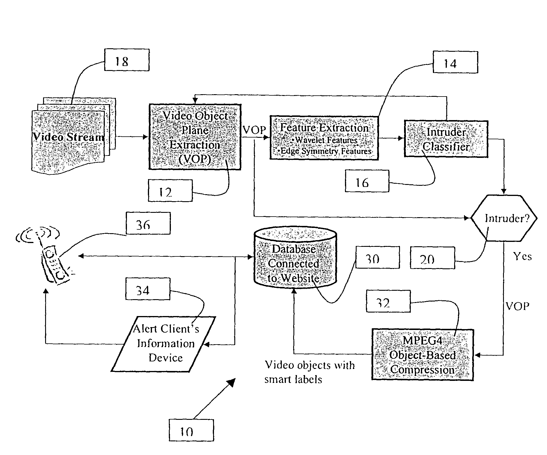
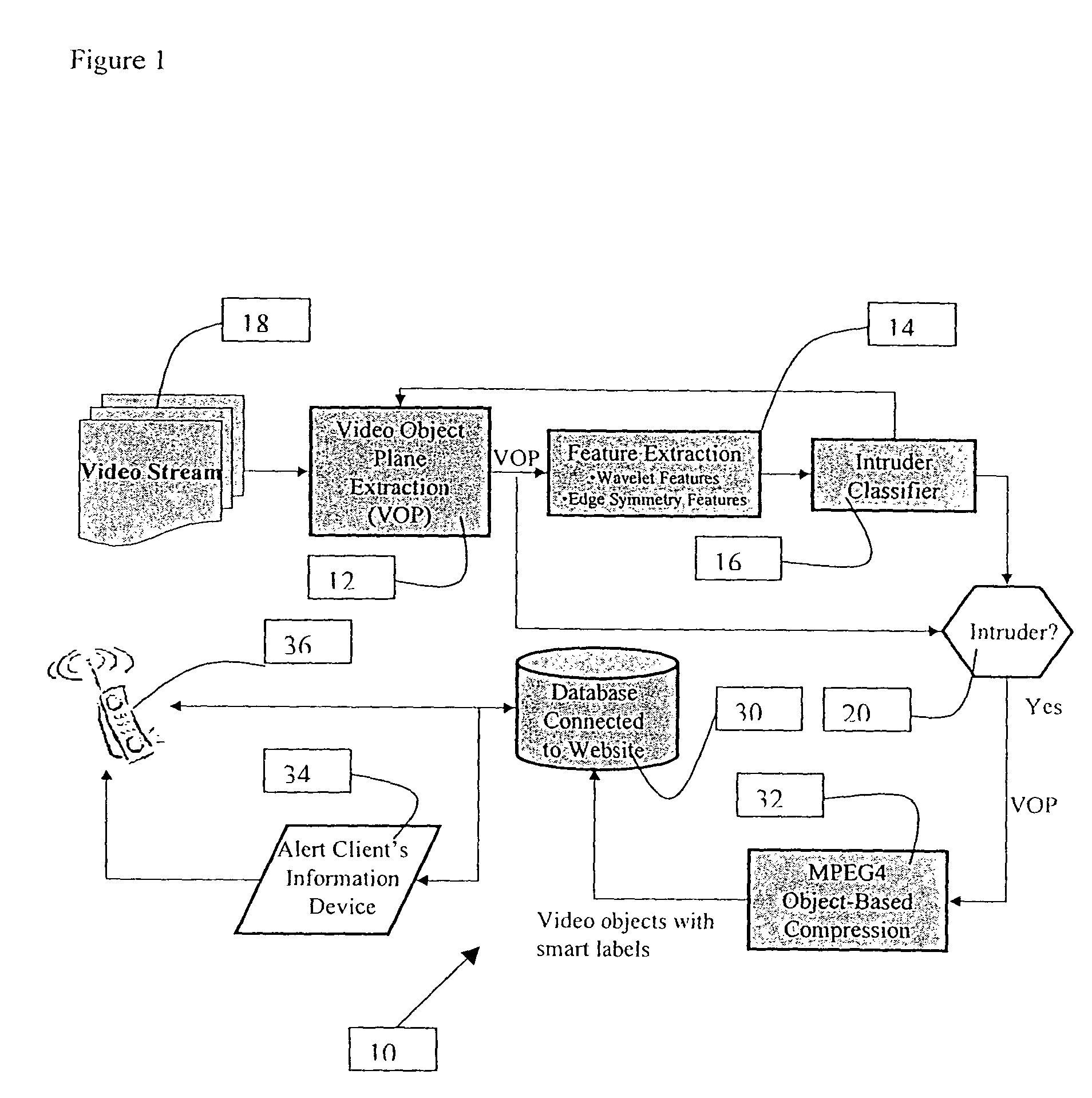
[0037]The present invention relates to an application-specific object-based segmentation and recognition technology. The present invention is designed for a number of applications, including the presently preferred embodiment disclosed herein, i.e., a home / business video-based security and monitoring market. A high-level block diagram of an embodiment of the present invention is shown in FIG. 1. This embodiment of the present invention can combine object segmentation, e.g., for the MPEG-4 video compression standard, specialized recognition algorithms, e.g., for detecting objects of interest, e.g., an intruder in the video scene, moving at least sometimes, through portions of the video scene, which can operate on the segmented objects. The output of the system can be stored, e.g., in a video database / server for use, e.g., for notifying users when suspicious activity has been detected to have occurred and supplying the user, e.g., with streaming video of the activity. The objects in t...


PUM


Abstract

A video detection and monitoring method and apparatus utilizes an application-specific object based segmentation and recognition system for locating and tracking an object of interest within a number of sequential frames of data collected by a video camera or similar device. One embodiment includes a background modeling and object segmentation module to isolate from a current frame at least one segment of the current frame containing a possible object of interest, and a classification module adapted to determine whether or not any segment of the output from the background modeling apparatus includes an object of interest and to characterize any such segment as an object segment. An object segment tracking apparatus is adapted to track the location within a current frame of any object segment and to determine a projected location of the object segment in a subsequent frame.

Description

[0001]This application claims the benefit of U.S. Provisional Application No. 60 / 405,346 filed Aug. 22, 2002.SOFTWARE SUBMISSION[0002]Accompanying this application is a duplicate set of CD-ROMs, labeled as “COPY 1 REPLACEMENT Jun. 11, 2004” and “COPY 2 REPLACEMENT Jun. 11, 2004”, respectively. Each disc includes a copy of the software files identified in Table 1, which are currently utilized by the inventors in implementing the invention as disclosed in this application. The entire contents of each CD-ROM are hereby incorporated by reference as if the source code and all files were printed out and included in the text of this application.[0003]TABLE 1Contents of Accompanying CD-ROMFilenameDate CreatedSize (bytes)AVIReader.cppJul. 2, 20034,150AVIReader.hJul. 2, 20031,120AVIWriter.cppAug. 26, 20025,028AVIWriter.hAug. 26, 20021,447classdata.datJul. 3, 20031,217,616d041002b_v.datApr. 10, 20023,849d041002b_w.datApr. 10, 200243,002Engine.hJul. 1, 20031,367Engineaviimage.cppJul. 3, 200329,...

Claims


Application Information

Patent Timeline
Patent Type & Authority Patents(United States)
IPC IPC(8): H04N7/18
CPCG06K9/00771G08B13/19602G08B13/19606G08B13/19608G08B13/19613G06V20/52
Inventor SRINIVASA, NARAYANMEDASANI, SWARUP S.OWECHKO, YURIKHOSLA, DEEPAK
Owner XLABS HLDG
Why Eureka
Try Eureka