
Method and apparatus for global motion estimation

a global motion and estimation technology, applied in the field can solve the problems of affecting the accuracy the complexity of local motion estimation is a computational barrier for practical use, and the hardware implementation is very costly for regular consumer electronics, so as to reduce the computational burden of global motion estimation, improve the robustness of global motion estimation results, and reduce the cost of hardware implementation

Inactive Publication Date: 2007-06-05
SHARP KK
View PDF14 Cites 46 Cited by
  • Summary
  • Abstract
  • Description
  • Claims
  • Application Information

AI Technical Summary

Benefits of technology

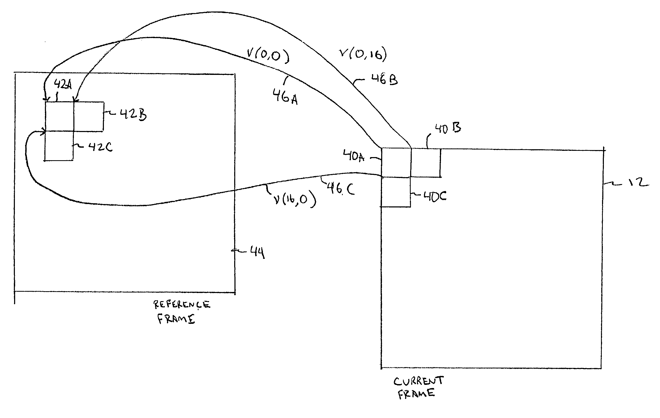
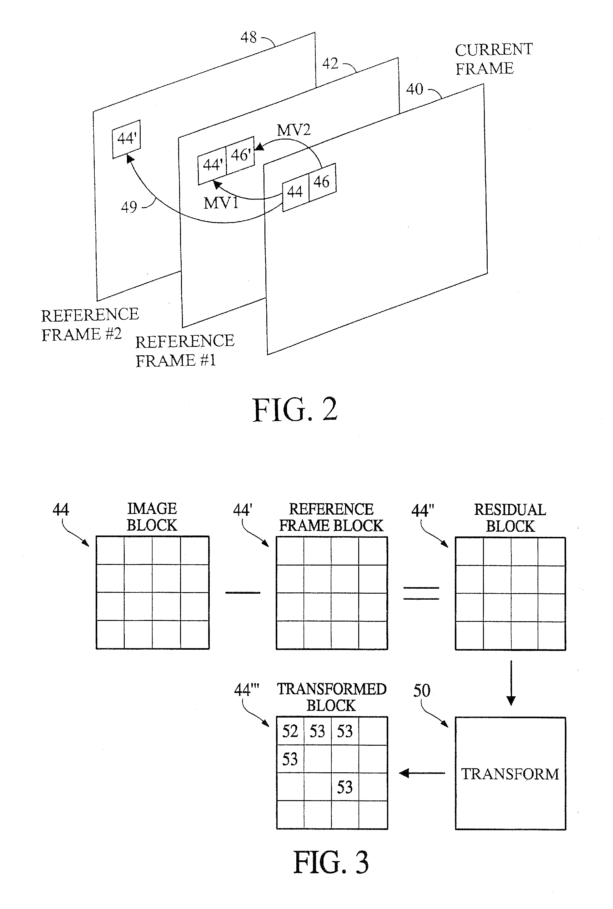
[0009]Different combinations of global motion parameters are estimated for a current frame interpolated to derive local motion vectors for individual image blocks. Image blocks in a reference frame identified by the local motion vectors are compared to the image blocks in the current frame. The estimated global motion parameters that provide the best match between the image blocks in the current frame and the reference frame are selected for encoding the current frame. Selected sub regions of temporally consecutive image frame s can be used in order to release the computational burden for global motion estimation and provide more robust global motion estimation results. A data truncation method can also be used to remove bias caused by foreground moving objects.

Problems solved by technology

However, in the discrete digital image domain, it is usually quite computationally expensive to solve the global motion parameters strictly following the mathematical models, which are well defined for the continuous space.
However, the complexity of local motion estimation is a computational barrier for practical usages.
But this hardware implementation is very costly for regular consumer electronics.
Another difficulty in global motion estimation is the existence of independently moving objects that introduce bias to the estimated motion parameters.
However, it is very difficult to segment the video objects.
However, the truncation utilizes a pre-fixed threshold, which is not well defined.
However, these techniques require large amounts of computational power.

Method used


Image

  • Method and apparatus for global motion estimation
  • Method and apparatus for global motion estimation
  • Method and apparatus for global motion estimation

Examples


Embodiment Construction

[0020]Global Motion Model

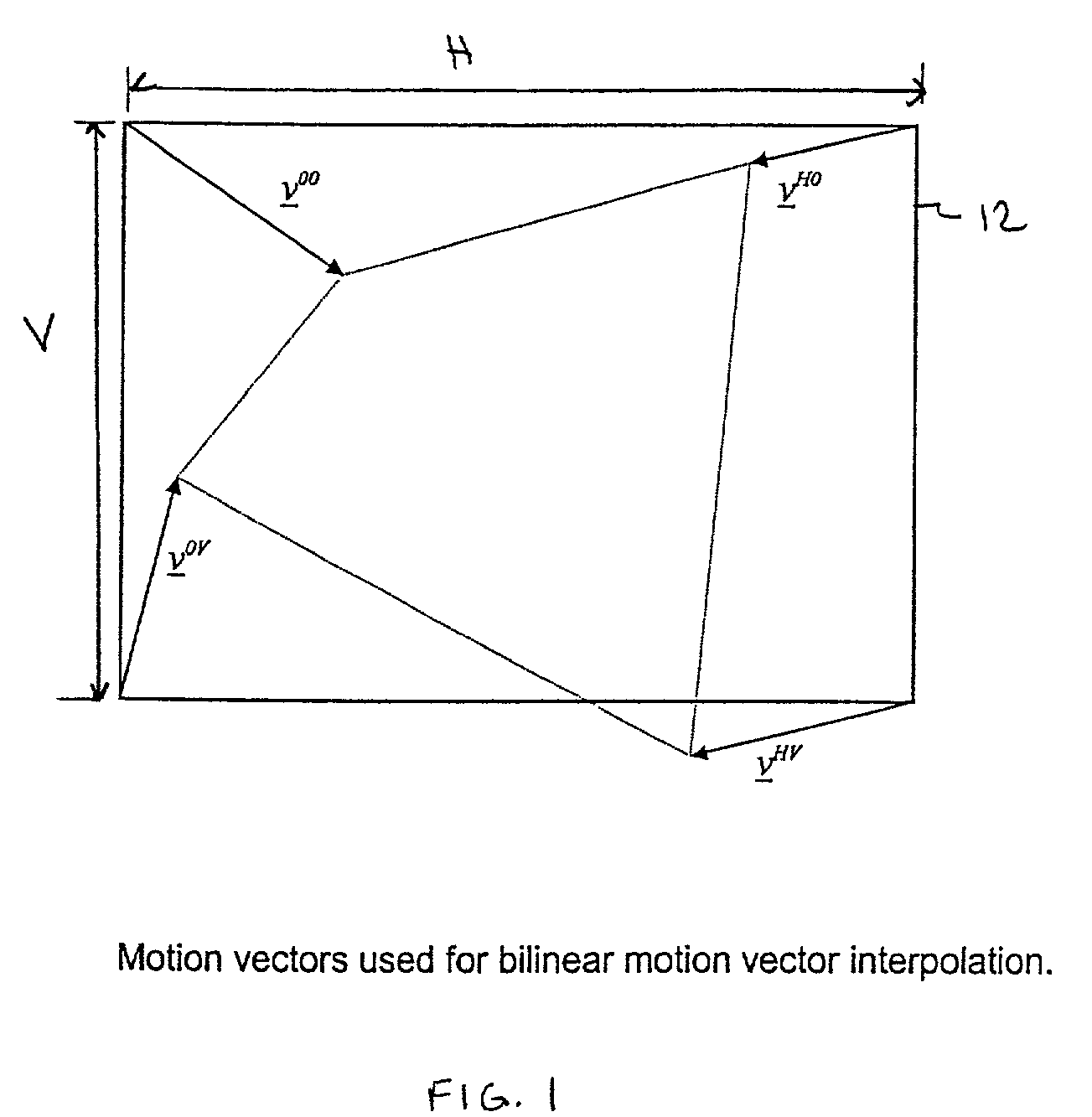
[0021]FIG. 1 shows an image frame 12 of size H×V. FIG. 1 illustrates the motion vectors used for bilinear motion vector interpolation, where v00, vH0, v0V and vHV represent the motion parameters of four a×a image blocks at the four corners (0,0), (H−a, 0), (0, V−a), and (H−a, V−a) of frame 12, respectively. The motion vector of an image block with its upper-left pixel at (x, y) can be derived as

[0022]v_⁡(x,y)=r_0+(xH-a)⁢r_x+(yV-a)⁢r_y+(xH-a)⁢(yV-a)⁢r_xy(1)[0023]where r0, rx, ry, and rxy are defined as the following

r0v00

rxvH0−v00

ry=v0H−v00

rxy=v00−vH0−v0V−vHV

The 4 global motion vectors (GMVs), v00, vH0, v0V, and vHV are solved directly instead of going through any transform matrices and parameters. Global motion vectors are alternatively referred to as global motion parameters.

[0024]FIG. 2 shows a flow chart explaining global motion estimation through a video scene. The process starts in box 20 by initializing the global motion vectors v00, vH0, v0V, and vHV i...


PUM


Abstract

Different combinations of global motion parameters are estimated for a current frame interpolated to derive local motion vectors for individual image blocks. Image blocks in a reference frame identified by the local motion vectors are compared to the image blocks in the current frame. The estimated global motion parameters that provide the best match between the image blocks in the current frame and the reference frame are selected for encoding the current frame. Selected sub regions of temporally consecutive image frame s can be used in order to release the computational burden for global motion estimation and provide more robust global motion estimation results. A data truncation method can also be used to remove bias caused by foreground moving objects.

Description

BACKGROUND[0001]Global motion estimation is used in video coding, video analysis, and vision-based applications. The global motion in an image sequence is usually considered as the relative motion of the camera with respect to the image background.[0002]There are a number of global motion modeling methods, which consider some or all of panning, zooming, rotation, affine motion, and perspective motion. Mathematically, these global operations can be described as different transform matrices. However, in the discrete digital image domain, it is usually quite computationally expensive to solve the global motion parameters strictly following the mathematical models, which are well defined for the continuous space.[0003]Some global motion estimation techniques conduct global motion estimation using a motion vector field obtained by a local motion estimation algorithm. Global motion parameters are then derived based on the mathematical models. However, the complexity of local motion estima...

Claims


Application Information

Patent Timeline
IPC IPC(8): H04N7/12G06K9/36H04N5/14H04N7/26H04N7/50
CPCH04N5/145H04N19/527H04N19/61
Inventor SUN, SHIJUN
Owner SHARP KK
Learn More