
LED light pipe structure

a technology of led light and light pipe, which is applied in the direction of waveguides, lighting and heating apparatus, instruments, etc., can solve the problems of consuming a lot of energy, and achieve the effect of good brightness and quality

Inactive Publication Date: 2007-06-05
LUMINA TECH
View PDF6 Cites 83 Cited by
  • Summary
  • Abstract
  • Description
  • Claims
  • Application Information

AI Technical Summary

Benefits of technology

The present invention provides an LED light pipe structure that uses a lamp holder to provide a direct-current power source. This allows the LED to generate a visible light for illumination that can be refracted and transmitted in an effective range. The light pipe can create an illumination that is bright and of high quality.

Problems solved by technology

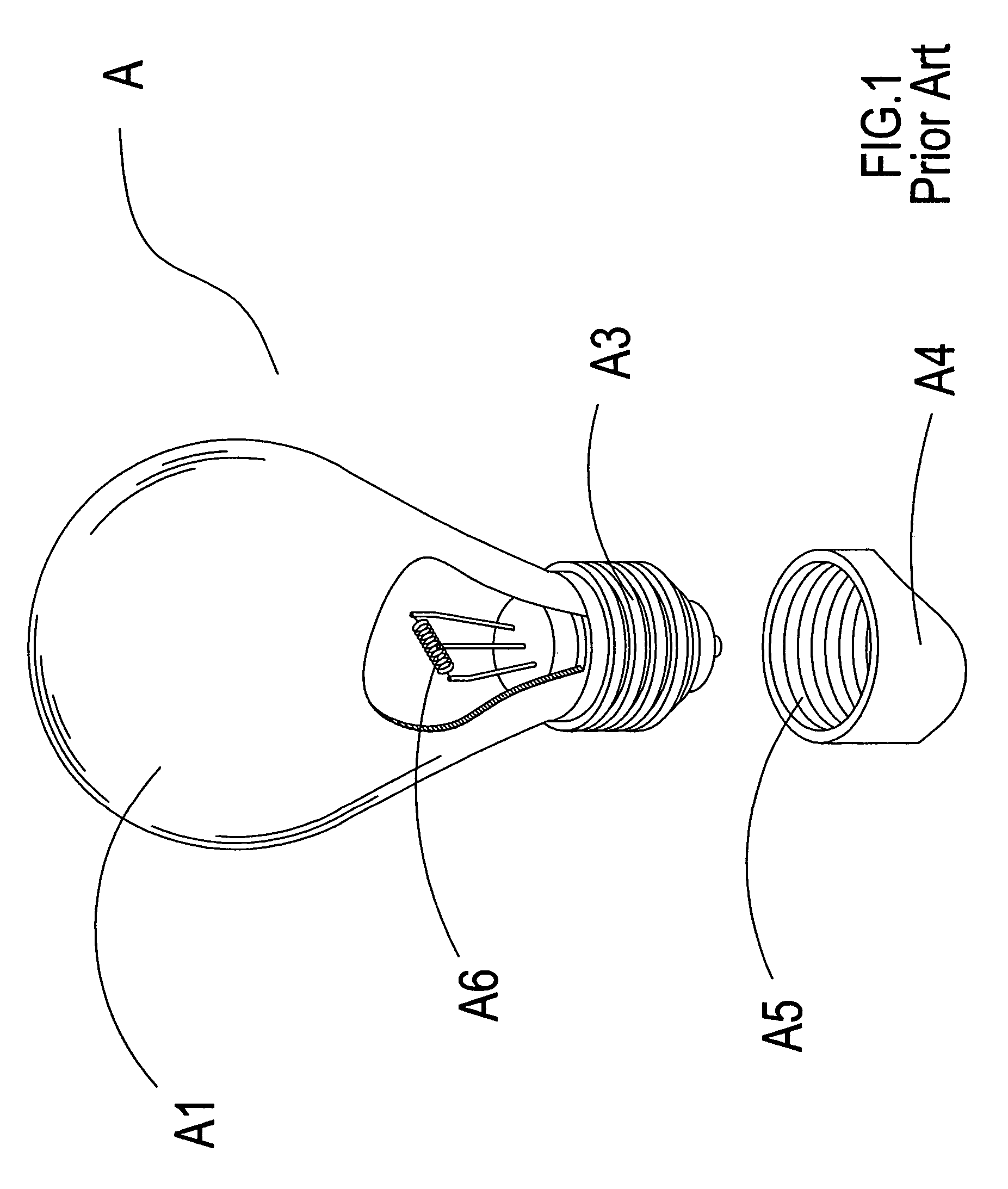
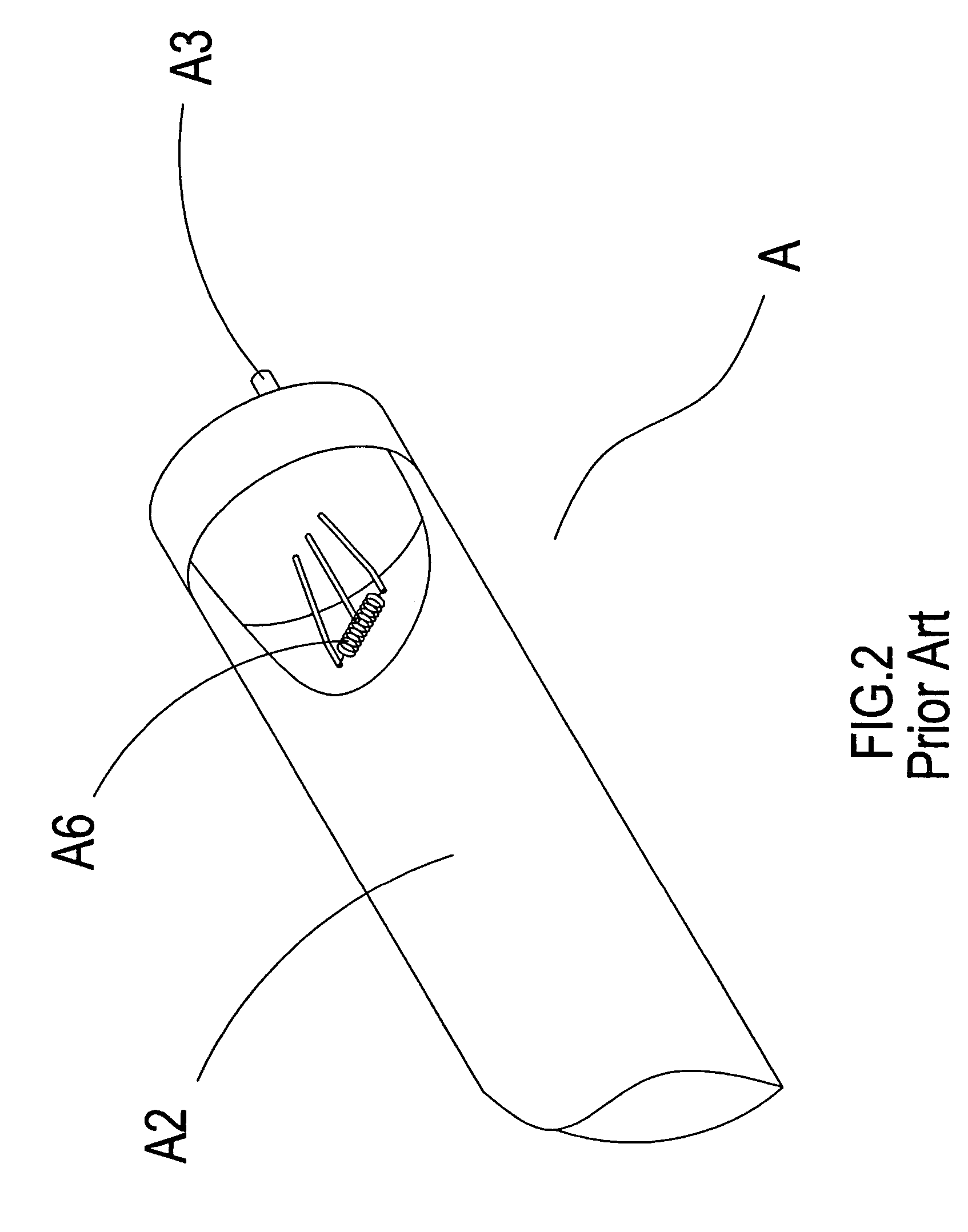
The technical problem addressed in this patent text is the high energy consumption and potential safety concerns associated with the use of traditional incandescent and fluorescent tubes in illuminant tubes. The invention aims to provide a solution to these shortcomings.

Method used


Image

  • LED light pipe structure
  • LED light pipe structure
  • LED light pipe structure

Examples


Embodiment Construction

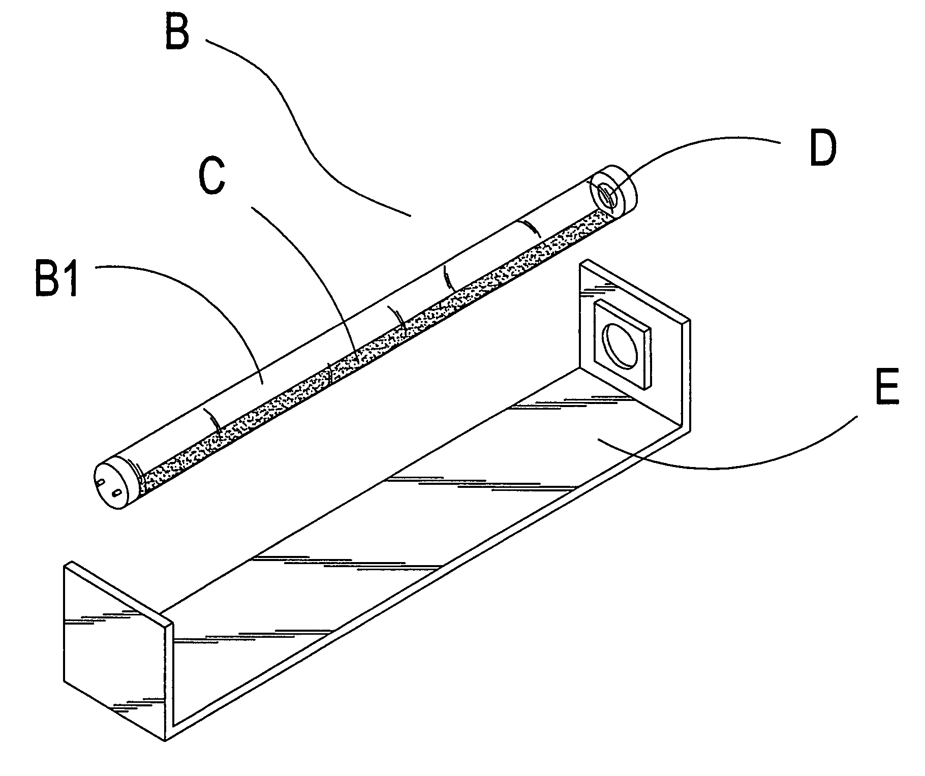
[0018]Referring to FIG. 3 and FIG. 4, the present invention comprises primarily a light pipe B, a light refraction plate C, a light emitting diode D, and a lamp holder E. The light pipe B is a cylindrical body B1 which is provided with a good guiding property and transmitting property, the light emitting diode D capable of generating a visible light for illumination is located at a tail end of the cylindrical body B1, and is corresponding to the light refraction plate C of light pipe B.

[0019]The light refraction plate C and the light pipe B are installed as one body with an electroplating, an affixing, or a coating method. When the light emitting diode D projects a visible light for illumination, the light refraction plate C can proceed with refracting and transmitting in an effective range.

[0020]In addition, a plurality of light emitting diodes D can be aligned and fixed at the tail end of the light pipe B. When the light pipe B is used for emitting light of different brightness, a...


PUM


Abstract

An LED light pipe structure includes a light pipe, a light refraction plate, and a light emitting diode which are integrally formed into one body, so as to enable the light emitting diode inside the light pipe to generate a visible light for illumination, through a voltage of direct-current power source provided by a lamp holder.
The visible light for illumination generated by the light emitting diode can be refracted and transmitted in an effective range by the light refraction plate, such that the light pipe can generate an illumination of good brightness and quality. In addition, when the light pipe is emplaced in environment of different illumination, the light emitting diode can be replaced with a light emitter of different light source, through that the light pipe can be fixed separately, such that the light pipe can be provided with functions of illuminating and identifying colors.

Description


Claims


Application Information

Patent Timeline
Owner LUMINA TECH
Features
  • Generate Ideas
  • Intellectual Property
  • Life Sciences
  • Materials
  • Tech Scout
  • Unparalleled Data Quality
  • Higher Quality Content
  • 60% Fewer Hallucinations
Learn More