Electrical system for a ship

a technology for electrical systems and ships, applied in the direction of vessel auxillary drives, emergency power supply arrangements, electric generator control, etc., can solve problems such as design disadvantages

Inactive Publication Date: 2007-06-05
SIEMENS AG
View PDF4 Cites 18 Cited by
  • Summary
  • Abstract
  • Description
  • Claims
  • Application Information

AI Technical Summary

Benefits of technology

[0004]According to an embodiment of the invention, the known hybrid sy...

Problems solved by technology

A mixed system such as this has admitte...

Method used


Image

  • Electrical system for a ship
  • Electrical system for a ship
  • Electrical system for a ship

Examples


Embodiment Construction

[0017]General Object of a Power Management System

[0018]The major task of the SIMOS PMA 71 power management system is to ensure that adequate electrical power is provided for all the operating states of the marine vessel. As the power demand on marine vessels increases, economic generation of power is, however, becoming virtually just as important as freedom from interruption.

[0019]The SIMOS PMA 71 automatic power generator system is based on the requirement of maintaining electrical power automatically during the various operating modes. In the event of faults in the on-board power supply system, all the necessary measures are initiated in order to supply the loads with electrical power with as little interruption as possible, while at the same time preventing damage.

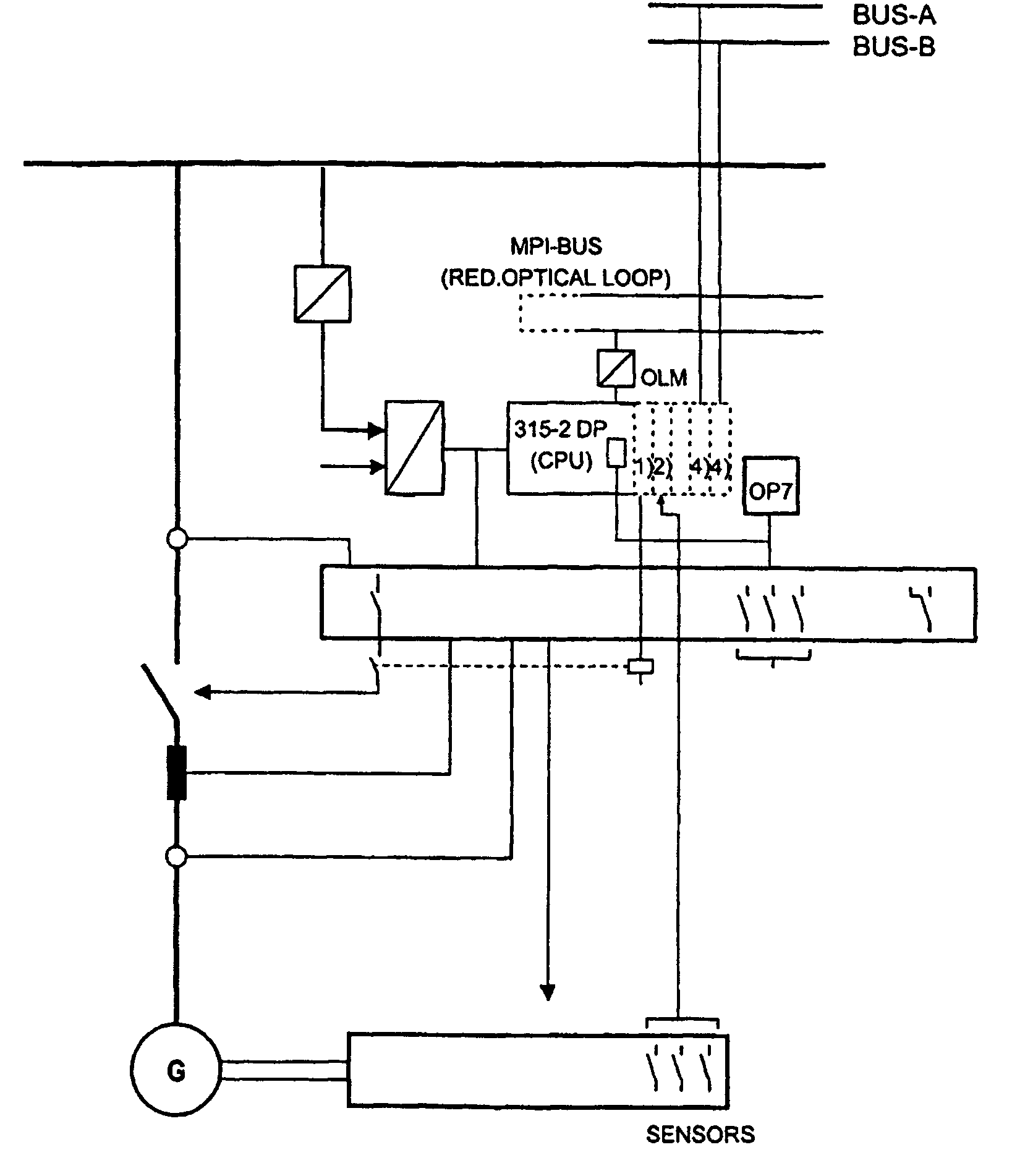
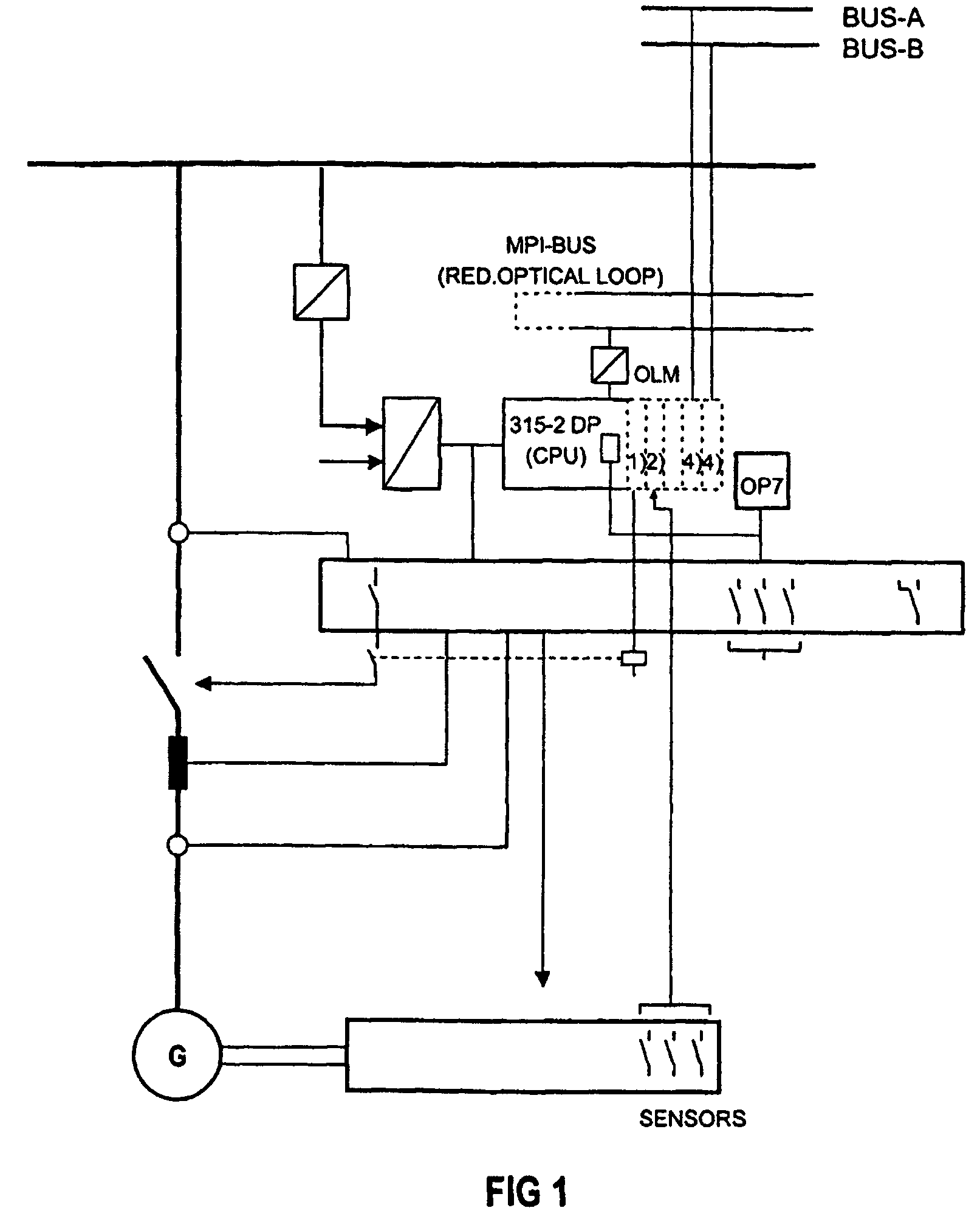
[0020]SIMATIC-S7 standard components are used for each machine unit, plus a generator protection device / measurement transducer and an OC 24V / DC 24V isolating transformer. The generator protection device / measurement tran...


PUM


Abstract

The invention relates to an electrical system for a ship, comprising generators, electrical consumers, such as electric motors, and an on-board power supply system with switchgears etc. as the components of the system. The electrical system is further characterized in that supplies sufficient electrical energy in all operating states of the ship and that the system components are automatically controlled by digitized standard modules.

Description

[0001]This application is the national phase under 35 U.S.C. § 371 of PCT International Application No. PCT / DE02 / 00151 which has an International filing date of Jan. 18, 2002, which designated the United States of America and which claims priority on German Patent Application number DE 101 04 892.0 filed Feb. 1, 2001, the entire contents of which are hereby incorporated herein by reference.FIELD OF THE INVENTION[0002]The invention generally relates to a marine electrical system. Preferably, it relates to a system having generators, electrical loads, such as electric motors and an on-board power supply system with switchgear assemblies etc. as system components, with the electrical system ensuring that adequate electrical power is provided in all operating states of the ship.BACKGROUND OF THE INVENTION[0003]Until now, measurement, control and regulation devices which operate on an analog basis have normally been used in maritime vessels, if appropriate with an associated digital cont...

Claims


Application Information

Patent Timeline
IPC IPC(8): G05D1/00G05D3/00B63J3/00H02H3/00H02H7/06H02J1/14H02J4/00H02J9/08H02P9/30
CPCH02J4/00H02J9/08H02P9/305B63J3/00B63J2003/002B63J2003/043H01H2071/006H02H3/00H02H7/06H02J1/14H02J2310/42
Inventor KAHLE, JENSKALLBACH, BERNDWILLER, HANS-PETER
Owner SIEMENS AG
Why Eureka
Try Eureka