Carabiner bungee cord terminus

a technology of bungee cords and bungee cords, which is applied in the direction of snap fasteners, buckles, mechanical devices, etc., can solve problems such as bringing users into danger, and achieve the effect of reliably secure and reliable engagement of a variety of anchors

Active Publication Date: 2007-06-12
HAMPTON PRODS INT
View PDF13 Cites 44 Cited by
  • Summary
  • Abstract
  • Description
  • Claims
  • Application Information

AI Technical Summary

Benefits of technology

[0003]Objects of the invention include: a bungee cord terminus which is extremely secure when in place; a sturdy bungee cord terminus which may reliably engage a v

Problems solved by technology

However, a carabiner which is simply passed through a ring may be turned with its small end away from the bungee cord

Method used


Image

  • Carabiner bungee cord terminus
  • Carabiner bungee cord terminus
  • Carabiner bungee cord terminus

Examples


Embodiment Construction

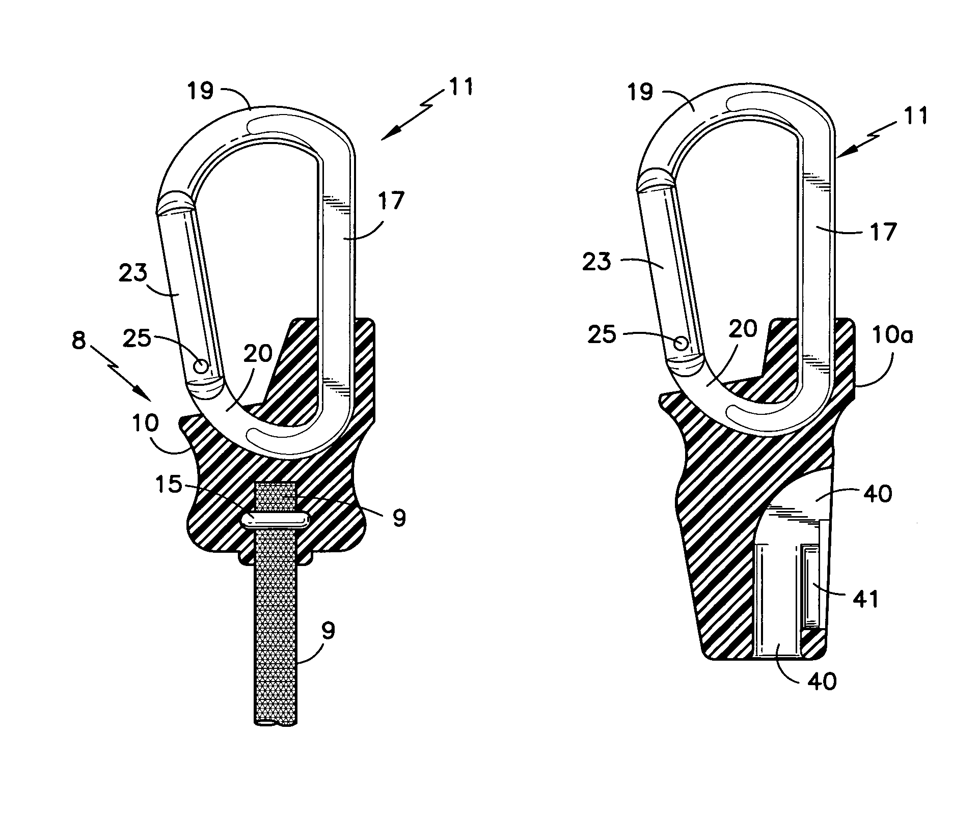
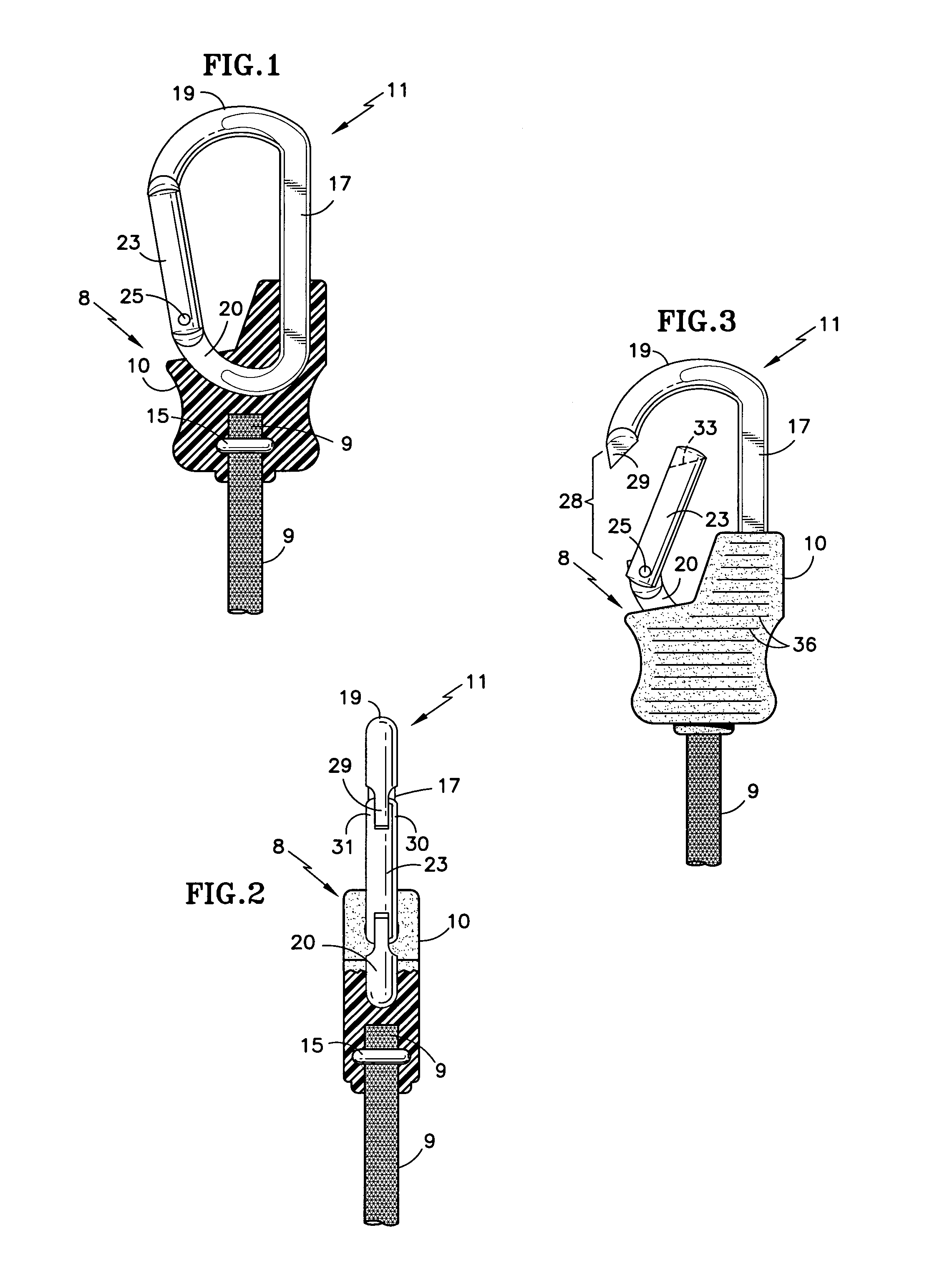
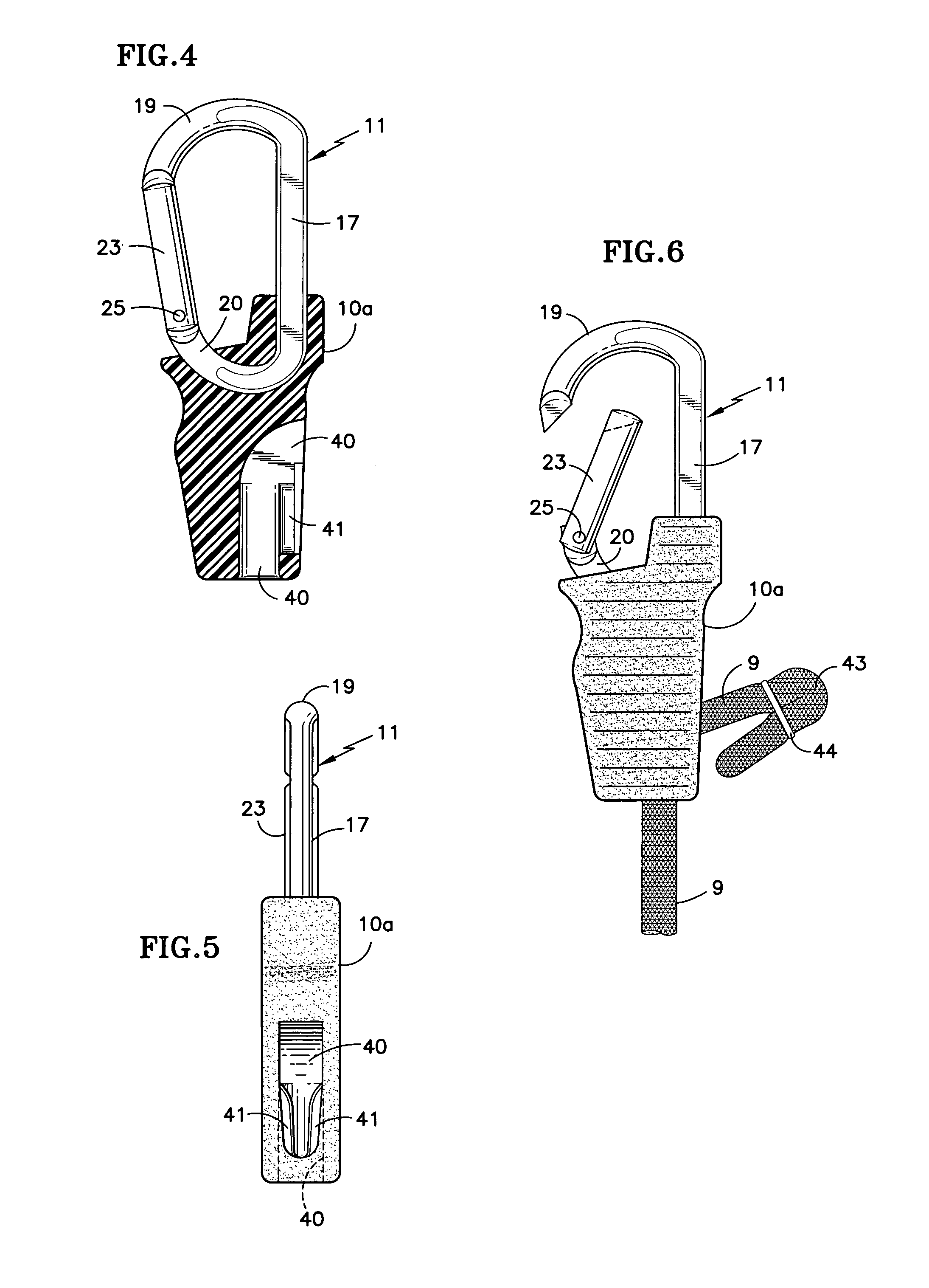
[0014]Referring to FIGS. 1 and 2, a terminus 8 for a bungee cord 9 comprises a molded, glass-filled plastic base 10 having a conventional carabiner 11 captured by being molded therein. In a preferred embodiment of the invention, the carabiner 11 comprises anodized aluminum.

[0015]The bungee cord 9 has a wire crimp 15, which may otherwise comprise a hog ring or other suitable crimp, which is molded, together with the end of the bungee cord 9, directly into the base 10, thus firmly anchoring the bungee cord 9 into the base 10.

[0016]The carabiner 11 may have a reduced thickness portion 17, or it may all comprise the same diameter. The carabiner 11 has a large rounded end 19 and a small rounded end 20 joined together by the portion 17. There is a closure gate 23 rotatably disposed to the small end 20 by means of a pivot 25. A spring (not shown) urges the closure gate 23 counterclockwise, into the closed position shown in FIGS. 1 and 2.

[0017]As seen in FIG. 3, the closure gate 23 may be p...


PUM


Abstract

A conventional carabiner (11) is molded directly into a plastic base (10), with the pivoted end of a closure gate (23) being toward the base. The base may also restrain a bungee cord (9) by having the end thereof and a wire crimp (15) molded into the base, or the base may have a bungee cord passageway (40) with cleat (41), into which the bungee cord may be pulled so as to lock the base in a desired position along the bungee cord.

Description

TECHNICAL FIELD[0001]This invention relates to a bungee cord (stretch cord) terminus which has a metal carabiner captured in a molded plastic base with an inwardly opening closure gate, spring-loaded toward the terminus, thereby to provide secure fastening through or about an anchor point.BACKGROUND ART[0002]Bungee cords are extremely common and used in a variety of ways. The most simple and common bungee cord terminus is a stiff wire hook which is crimped to the end of the bungee cord. The position of one form of terminus known in the art is adjustable along the length of the cord; in other forms the position is fixed. A variety of still other forms are known to provide a variety of features to suit different applications. Many have open hooks; others rely on thin plastic closures.DISCLOSURE OF INVENTION[0003]Objects of the invention include: a bungee cord terminus which is extremely secure when in place; a sturdy bungee cord terminus which may reliably engage a variety of anchors;...

Claims


Application Information

Patent Timeline
IPC IPC(8): F16B45/02F16B45/00
CPCF16B45/02Y10T24/45435Y10T24/314Y10T24/4755F16B45/023
Inventor SELBY, RICKY W.KELLEY, III, HAYWARD KENDALLGAST, ROBERT LEETHOMAS, DONALDHUNT, RAYMOND N.
Owner HAMPTON PRODS INT
Why Eureka
Try Eureka