Device for absorbing floor-landing shock for legged mobile robot

a mobile robot and floor-landing technology, which is applied in the field of landing shock absorbers, can solve the problems of sudden increase in hydraulic oil pressure, affecting the size reduction and weight reduction of each leg, and unstable posture of the robot, so as to enhance the damping effect of the landing shock absorber of the present invention, enhance the impact load reduction effect, and enhance the effect of compressible fluid outflow resistan

Inactive Publication Date: 2007-06-12
HONDA MOTOR CO LTD
View PDF10 Cites 29 Cited by
  • Summary
  • Abstract
  • Description
  • Claims
  • Application Information

AI Technical Summary

Benefits of technology

[0011]According to the present invention (the first invention), during the landing motion of each leg, the variable capacity element in an inflated state is compressed with the compressible fluid in the interior portion thereof, and resultingly, pressure of the compressible fluid increases. At this time, the pressured compressible fluid in the variable capacity element flows out of the variable capacity element with the outflow resistance by the inflow / outflow means. This allows motion energy of the leg to be attenuated. Additionally, in this situation, some of the motion energy of the leg is transformed to elastic energy of the compressible fluid to be absorbed by a spring property of the compressible fluid, and furthermore, the elastic energy is dissipated by the outflow resistance of the compressible fluid from the variable capacity element. While such an operation prevents a generation of an instantaneous sudden change of the floor reaction force acting on the leg through the variable capacity element and the compressible fluid in the interior portion thereof, the impact load acting on the leg during the landing motion of the leg (the transient floor reaction force) is reduced. Therefore, according to the present invention, the impact load at the time of the landing of the leg may smoothly be reduced and a good shock absorbing effect may be obtained.
[0027]Additionally, the present invention (the fist through the thirteenth inventions) is preferred when the legged mobile robot is a robot that a position and a posture of the foot mechanism is controlled by compliance control so as to allow a moment about an axis in a horizontal direction for the floor reaction force acting on the foot mechanism of each leg (for example, a moment detected by a six-axis force sensor or the like) to follow a predetermined desired moment (a fourteenth invention). That is to say, a spring constant of the compressible fluid is decreased by the pressure of the variable capacity element according to the landing motion of the leg, and consequently, a gain of the control (a compliance gain) may be enhanced, while ensuring stability of a control system for the compliance control. As a result, a following-property of a moment about the axis in the horizontal direction acting on each foot mechanism to the desired moment may be enhanced. Consequently, the stability of the posture of the robot may be ensured, while properly reducing the impact load at the time of the landing. Additionally, in particular, in the aforementioned fourth invention provided with multiple bag-like members, when the compliance control is performed, the moment about the axis in the horizontal direction may be acted on each foot mechanism by a ground contact for any of multiple bag-like members during the landing motion of the leg. Consequently, the stability of the posture of the robot may effectively be ensured by the above compliance control, so that the floor reaction force acting on the leg may be put into a steady state at an early stage.

Problems solved by technology

When this impact load is high, rigidity of each portion of each leg needs to be enhanced in order to resist the load, and furthermore, this will interfere with a size reduction and a weight reduction of each leg.
However, in the shock absorber, as a result of the use of the hydraulic oil, particularly, when a moving speed of a robot is fast, pressure of the hydraulic oil suddenly increases at the instant when the ground-contacting element touches the ground.
However, in a situation like this, a damping effect caused by a flow of the hydraulic oil (an attenuating effect of motion energy) decreases and a vibration of a floor reaction force immediately after the landing motion of the foot mechanism tends to be generated, and resultingly, a posture of the robot tends to be unstable.
Furthermore, in the shock absorber, as a result of the use of the hydraulic oil, weight of the shock absorber will be heavy, resulting in interfering with a weight reduction of the robot.
Consequently, the impact load acting on the ground-contacting element may act in a direction that crosses a movable direction thereof depending on a geometry of a floor, so that the impact load may not adequately be reduced, and a damage of the shock absorber may be generated.

Method used


Image

  • Device for absorbing floor-landing shock for legged mobile robot
  • Device for absorbing floor-landing shock for legged mobile robot
  • Device for absorbing floor-landing shock for legged mobile robot

Examples


first embodiment

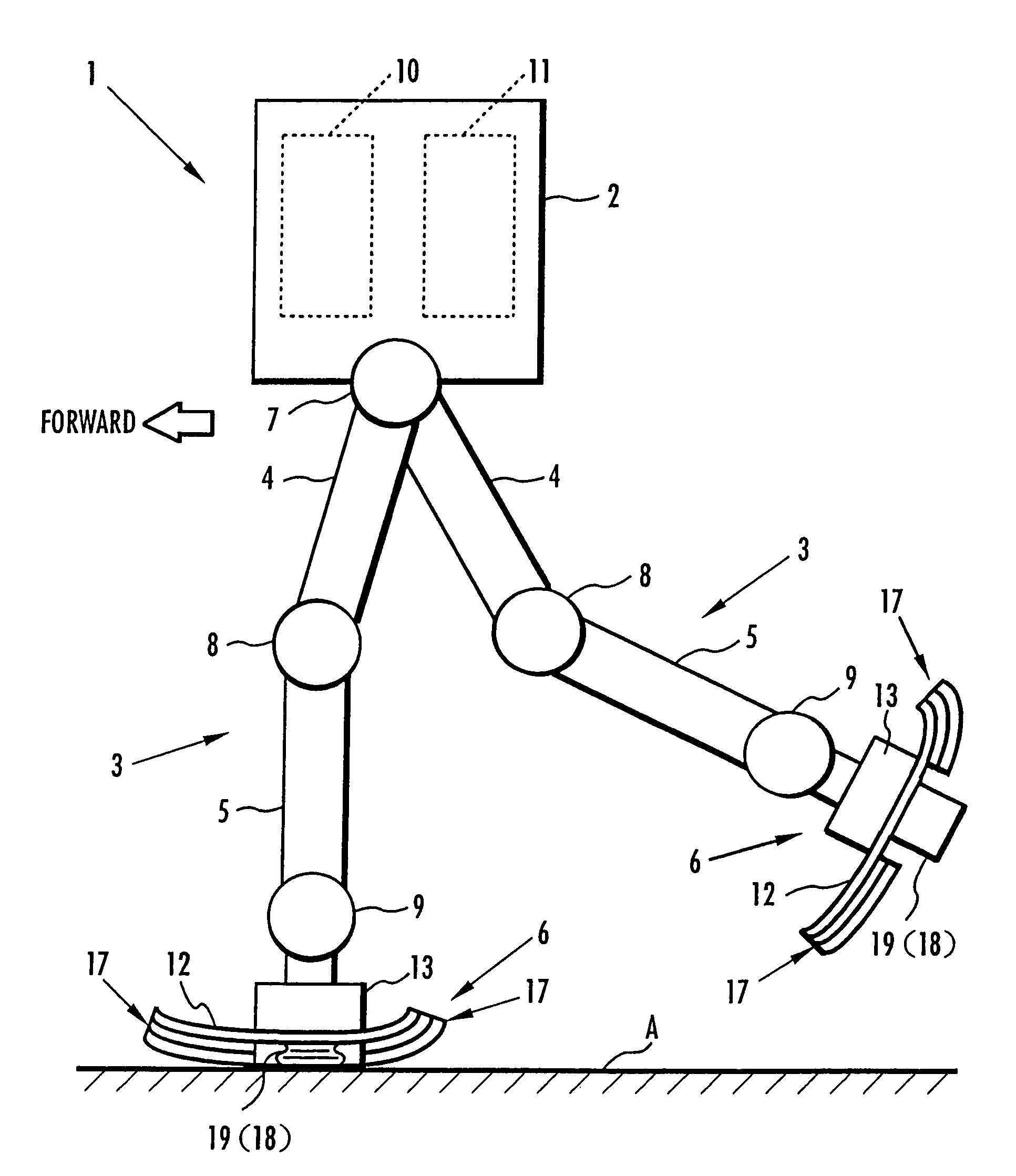
[0048]Referring to FIGS. 1 through 5, the present invention is described. FIG. 1 is a side view showing an overall basic configuration of a legged mobile robot 1 of the present embodiment in schematic form. As shown in FIG. 1, for example, the legged mobile robot 1 of the present embodiment is a biped mobile robot comprising a pair of (two) legs 3, 3 extendedly disposed from a lower end portion of its upper body 2 (torso). Further, arms and a head may be attached on the upper body 2.

[0049]Each leg 3 is constructed by connecting a thigh 4, a lower leg 5, and a foot mechanism 6 in the order listed through a hip joint 7, a knee joint 8, and an ankle joint 9 from the lower end portion of the upper body 2. More specifically, each leg 3 is adapted to be configured with the thigh 4 extendedly disposed from the lower end portion of the upper body 2 through the hip joint 7, the lower leg 5 connected to a far end portion of the thigh 4 through the knee joint 8, and the foot mechanism 6 connec...

third embodiment

[0082]Subsequently, referring to FIG. 7(a) and FIG. 7(b), the present invention is described. FIG. 7(a) and FIG. 7(b) are cross sectional views showing a configuration of infow / outflow means of a landing shock absorbing device of the present embodiment. Further, the present embodiment differs from the second embodiment only in the configuration of the inflow / outflow means, so that regarding component portions or function portions identical to those of the second embodiment, the reference numerals identical to those of the second embodiment are used, thereby omitting descriptions thereof.

[0083]As shown in FIG. 7, in the landing shock absorbing device in the present embodiment, inflow / outflow means 23 is equipped with a hollow valve chamber element 24 upwardly extended from the foot plate member 12 of each foot mechanism 6 and a discoidal valve element 25 provided in an interior of this valve chamber element 24. The interior of the valve chamber element 24 is communicated with the ins...

second embodiment

[0084]The valve element 25 is provided with the flow-passing hole 25a drilled in the center portion thereof, and a notch portion 25b on one end portion (a left end portion in the figure. Additionally, the valve element 25 is adapted to be pivotable in a direction that the end portion with the notch portion 25b moves up and down, having a spindle 26 provided on the other end portion (a right end portion in the figure) as a supporting point. In this case, the valve element 25 is pivotable between a state that its top face portion abuts the upper end portion of the valve chamber element 24 as shown in FIG. 7(a) and a state that a lower end portion of the valve element 25 (an end portion having the notch portion 25b) abuts the lower end portion of the valve chamber element 24 as shown in FIG. 7(b), and in the state of FIG. 7(a), the notch portion 25b of the valve element 25 is closed and covered by the upper end portion of the valve chamber element 24 so as to allow the flow-passing hol...


PUM


Abstract

A landing shock absorbing device 18 disposed in a foot mechanism 6 of a leg of a robot, wherein an inflatable bag-like member 19 (a variable capacity element) is provided at a ground-contacting face side of the foot mechanism 6. The bag-like member 19 is constructed of an elastic material such as rubber and has a restoring force. An interior portion of the bag-like member 19 is communicated with the atmosphere side through a flow passage 20. During a landing motion of the leg, the bag-like member 19 makes contact with the ground to be compressed, and the air in the interior portion thereof flows out into the atmosphere through the flow passage 20, so that its outflow resistance is generated. Accordingly, a landing shock is reduced. In a lifting state of the leg, the restoring force of the bag-like member 19 allows the bag-like member 19 to be inflated while the air flows into the interior portion thereof. An impact load during the landing of the leg of the legged mobile robot may smoothly be reduced in a light-weight configuration.

Description

TECHNICAL FIELD[0001]The present invention relates to a landing shock absorber for reducing an impact load during a landing motion of a leg of a legged mobile robot.BACKGROUND ART[0002]In a legged mobile robot such as a biped mobile robot equipped with a plurality of legs, each leg is brought into contact with a floor through a ground-contacting face portion of a foot mechanism provided on a far end portion thereof. More particularly, the foot mechanism is a mechanism connected to a joint on the farthest end side of each leg (an ankle joint). The legged mobile robot moves by lifting and landing motions of each leg. More particularly, the lifting and landing motions are a repetition of motions that while at least one leg of a plurality of legs as a supporting leg maintains a foot mechanism of the supporting leg in a ground-contacting state, the other leg as a free leg lifts a foot mechanism of the free leg from its ground-contacting location into the air and moves the same, and make ...

Claims


Application Information

Patent Timeline
Patent Type & Authority Patents(United States)
IPC IPC(8): B62D57/032A63H11/18B25J5/00B25J19/00F16F9/04
CPCB25J19/0091B62D57/032F16F9/0481B25J5/00
Inventor TAKENAKA, TORUGOMI, HIROSHIHAMAYA, KAZUSHITAKEMURA, YOSHINARIMATSUMOTO, TAKASHIYOSHIIKE, TAKAHIDENISHIMURA, YOICHIAKIMOTO, KAZUSHIYOKOYAMA, TARO
Owner HONDA MOTOR CO LTD
Why Eureka
Try Eureka