Valve for controlling a fluid

a valve and fluid technology, applied in the direction of valve operating means/release devices, mechanical equipment, machines/engines, etc., can solve the problems of shortening high wear demands, and inability to reliably ensure the service life of the valve, and achieves uniform interior diameter, good concentricity properties, and simple and cost-effective manner.

Inactive Publication Date: 2007-06-12
ROBERT BOSCH GMBH
View PDF8 Cites 7 Cited by
  • Summary
  • Abstract
  • Description
  • Claims
  • Application Information

AI Technical Summary

Benefits of technology

[0005]The valve according to the present invention for controlling a fluid, in particular for controlling a gas, in which the armature is guided along an armature sleeve which is situated in the housing sleeve, has the advantage that the armature sleeve is manufacturable in a simple and cost-effective manner to have a uniform interior diameter and thus good concentricity properties which have an advantageous effect on the valve's continuous operation properties. Due to the use of the armature sleeve, an additional guide sleeve is present which ensures optimized guide conditions and thus only a slight tilting tendency of the armature and therefore little wear in the guide area of the armature and also in the valve seat area.
[0006]Moreover, the uniform interior diameter of the armature sleeve makes it possible that, for producing an exterior diameter corresponding to the armature sleeve, the armature may be machined using a simple serial process, such as a continuous grinding process, since only one guide diameter in particular is necessary on the armature.
[0007]The armature sleeve is integratable into the known valve in a simple manner so that it is also integratable into the housing sleeve in existing series manufacturing processes without great expense.

Problems solved by technology

The problem in the case of the known gas valve is that the dry and gaseous medium to be controlled results in high wear demands which necessitate high-precision guiding of the armature.
This cannot be reliably ensured by the previously used guiding of the armature in the housing sleeve since the housing sleeve may have the problem of concentricity variations and diameter tolerances resulting from the deep-drawing processes used in the manufacture.
The eccentricities and the diameter variations increase the tilting tendency of the armature and may in turn shorten the valve's service life.

Method used


Image

  • Valve for controlling a fluid
  • Valve for controlling a fluid
  • Valve for controlling a fluid

Examples


Embodiment Construction

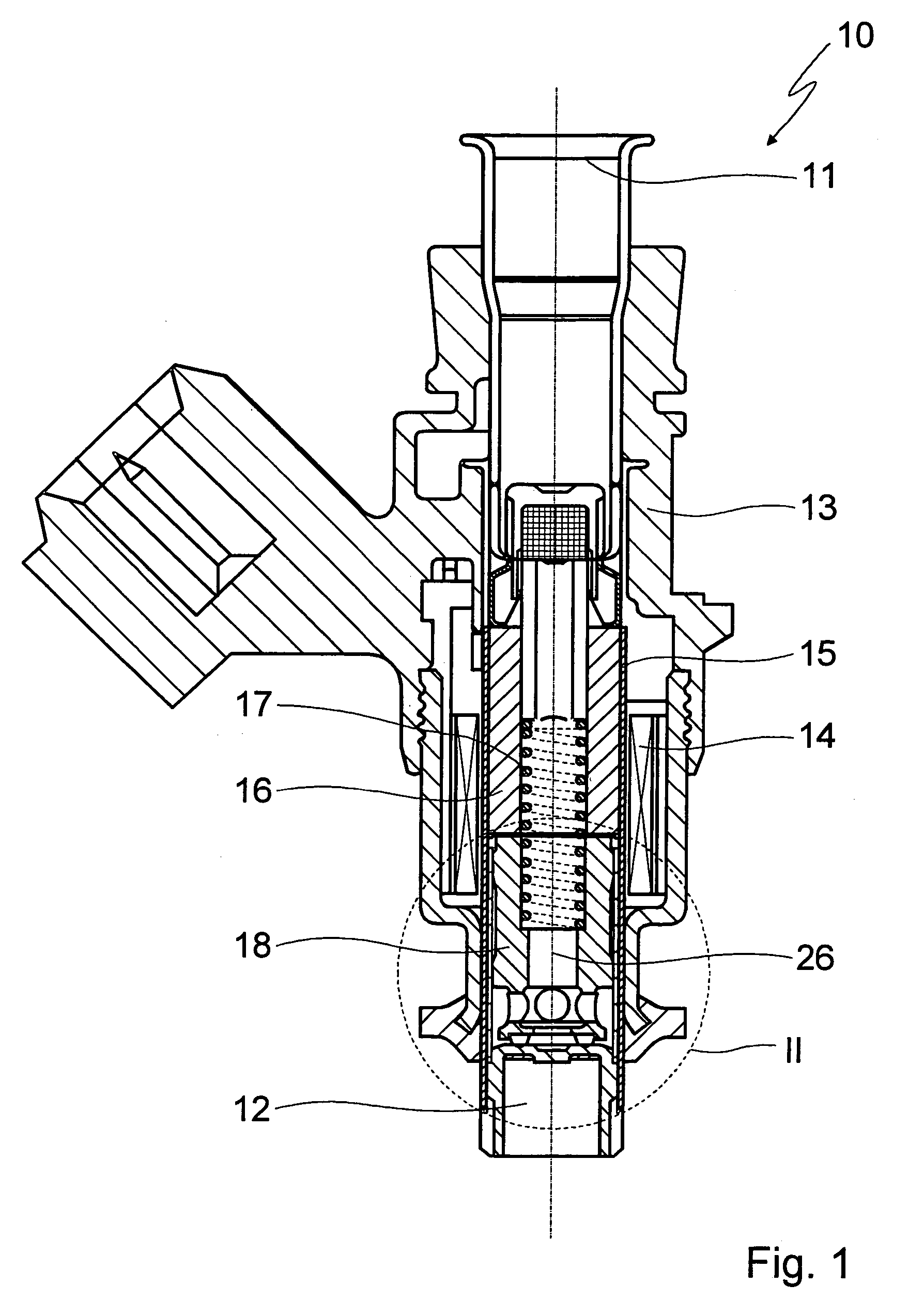
[0020]FIG. 1 shows a gas valve 10 which is designed for integration into a fuel cell or into a gas-powered engine and which is used for regulating a hydrogen flow or an NG (natural gas) flow from an inflow side 11 to an outflow side 12.

[0021]Gas valve 10 includes a multi-part housing 13 which accommodates a magnetic coil 14 and a housing sleeve 15.

[0022]An essentially tubular plug 16 is fixed in housing sleeve 15, a helical spring 17, used as a pre-stressing spring, being inserted into the plug, and the helical spring acting on an armature 18 which is situated in housing sleeve 15 in a longitudinally displaceable manner.

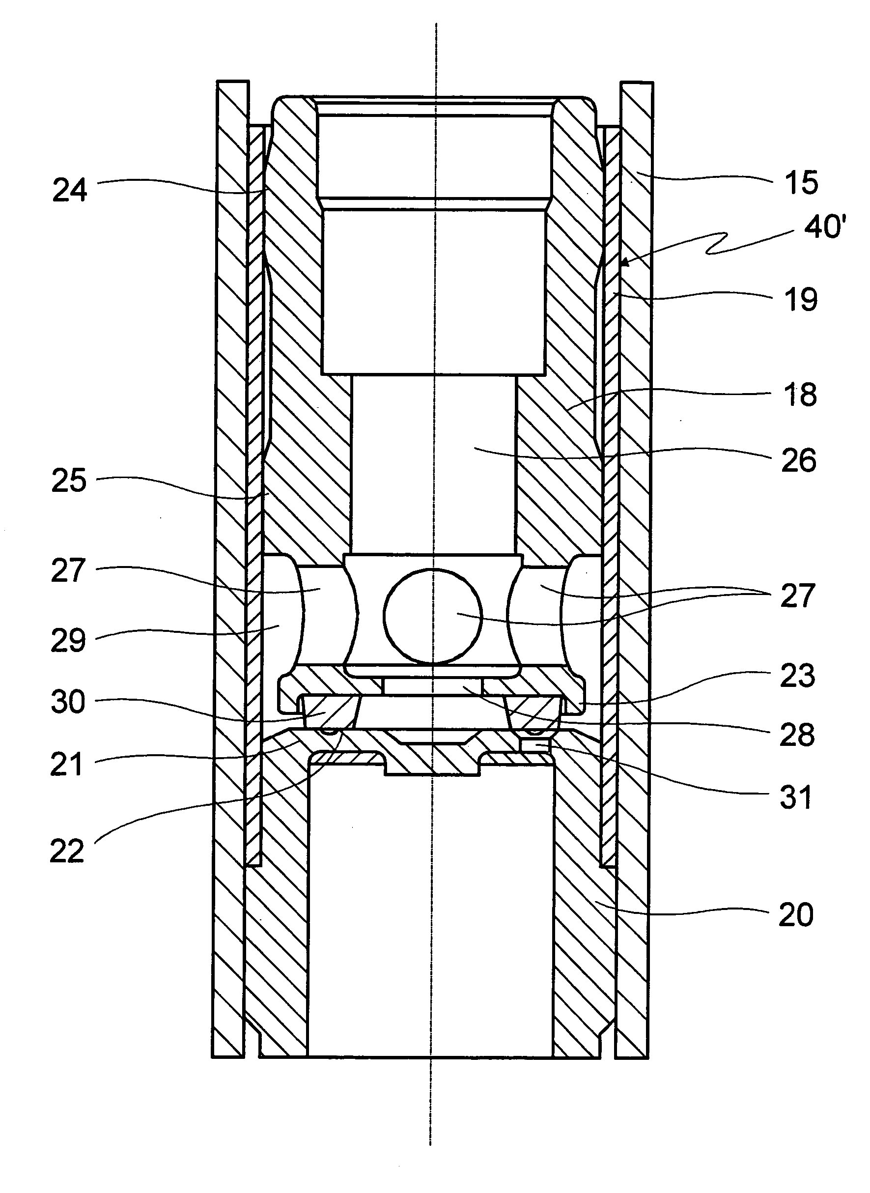
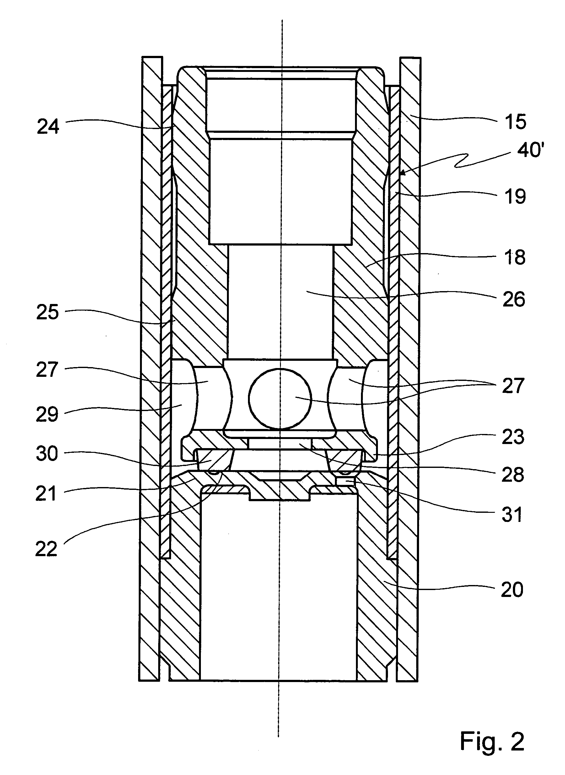
[0023]As FIG. 2 particularly shows, armature 18 is guided along an armature sleeve 19 which is clamped onto a cup-shaped component 20 the bottom area of which forms a seating plate 21 on which a valve seat 22 is situated for a front area 23 of armature 18 used as a valve-closing element. For securing purposes, armature sleeve 19 is welded to cup-shaped component 20 w...


PUM


Abstract

A valve for controlling a fluid, in particular for controlling a gas. The valve includes a valve housing having a housing sleeve and an electromagnetic actuator for an armature which is guided in an axially displaceable manner and which cooperates with a valve seat situated on a seating plate so that a fluid flow through outflow orifices in the seating plate is controllable. The armature is guided along an armature sleeve which is situated in the housing sleeve.

Description

FIELD OF THE INVENTION[0001]The present invention is directed to a valve for controlling a fluid, in particular for controlling a gas.BACKGROUND INFORMATION[0002]A valve is known from practice and is usable, for example, as a gas control valve in a fuel cell or also in a gas-powered engine.[0003]The known valve includes a valve housing which accommodates an in particular electromagnetic actuator for an armature and is provided with a housing sleeve in which the armature is guided in an axially displaceable manner. The armature is used as a valve-closing element and cooperates with a valve seat situated on a seating plate so that a fluid flow through outflow orifices in the seating plate is controllable.[0004]The problem in the case of the known gas valve is that the dry and gaseous medium to be controlled results in high wear demands which necessitate high-precision guiding of the armature. This cannot be reliably ensured by the previously used guiding of the armature in the housing...

Claims


Application Information

Patent Timeline
Patent Type & Authority Patents(United States)
IPC IPC(8): F16K31/06F02M21/02F02M51/06
CPCF02M51/0667F16K31/0651F16K31/0655F02M21/0266F02M21/0254Y02T10/32Y02T10/30
Inventor MILLER, FRANKOKRENT, ELMAR
Owner ROBERT BOSCH GMBH
Why Eureka
Try Eureka