Mold lock with lubricating grooves

a technology of lubricating grooves and mold locks, which is applied in the direction of dough shaping, manufacturing tools, applications, etc., can solve the problems of mold locks that cannot meet tolerances, mold lock alignment degrades and becomes less accurate, and mold locks are subject to wear and tear. , to achieve the effect of reducing the harmful line-to-line metal conta

Inactive Publication Date: 2007-06-12
LEMKIN JACK
View PDF8 Cites 19 Cited by
  • Summary
  • Abstract
  • Description
  • Claims
  • Application Information

AI Technical Summary

Benefits of technology

[0011]With the shortcomings of known mold locks clearly in mind, the inventor has devised a mold lock with the ability to supply a lubricating film to the walls of the mold lock to prevent, or at last significantly reduce, the harmful line-to-line metal contact. The tongue of the T-shaped member is drill

Problems solved by technology

However, as the mold is operated, at high speeds, during extended production runs, the alignment of the two halves of the mold degrades and becomes less accurate.
Side locks 128, 129 start to wear and are unable to fully compensate for the reduced accuracy, and the mold loses its ability to produce products within acceptable tolerances.
However, all mold locks ar

Method used


Image

  • Mold lock with lubricating grooves
  • Mold lock with lubricating grooves
  • Mold lock with lubricating grooves

Examples


Embodiment Construction

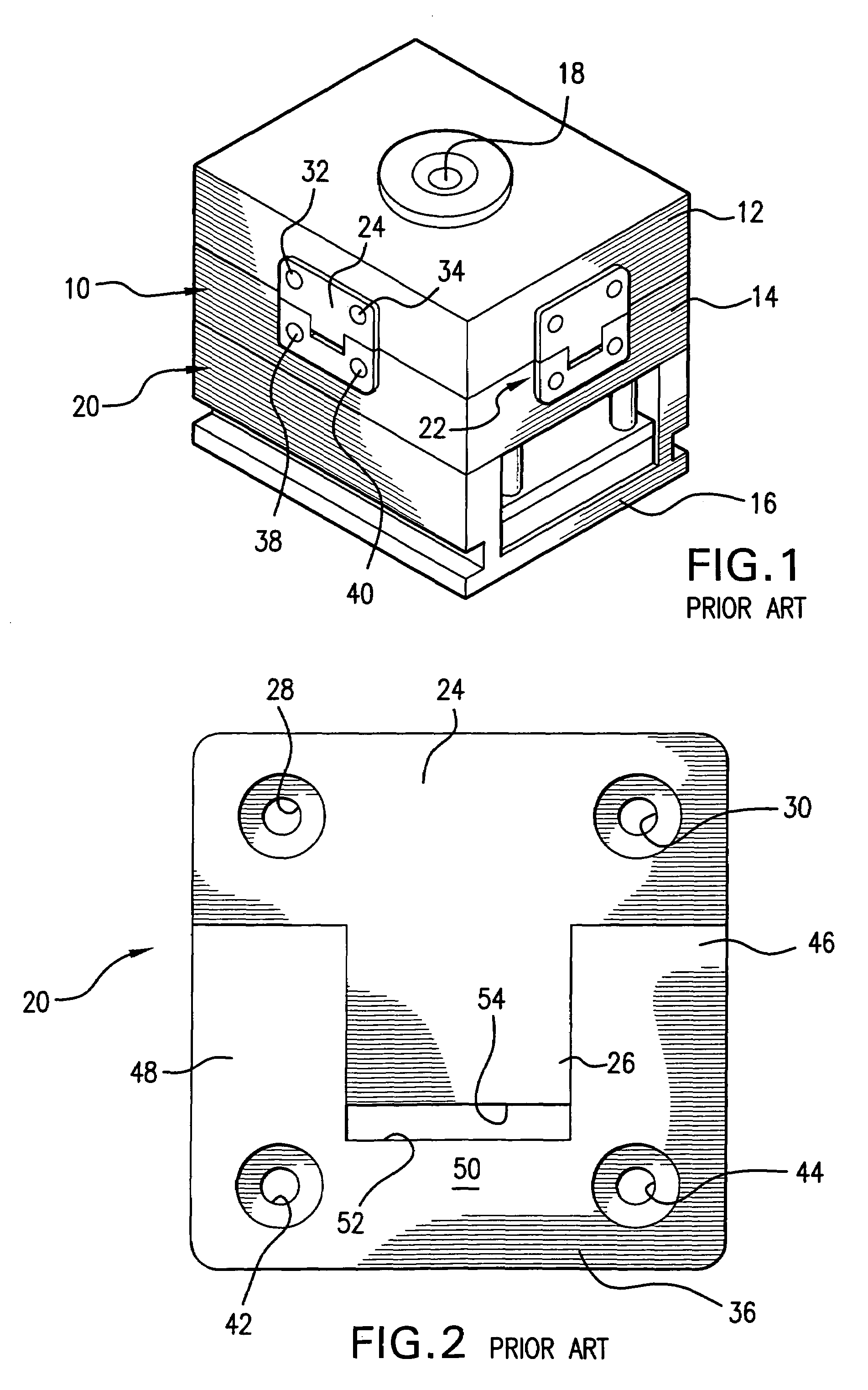
[0025]FIGS. 1 and 2, designated as PRIOR ART, show a conventional mold assembly 10, comprising a first mold half 12, a second cooperating mold half 14, and a base 16 for supporting the mold halves. An injection port 18 in first mold half 12 introduces the molten plastic into the interior of the mold assembly, and a die in the cavity (not shown) defined in the interior of the mold determines the shape of the object being molded. The mold halves are movable relative to one another, so that the cavity is sealed during the molding process, but are separated so that the molded object can be removed at the end of the molding process.

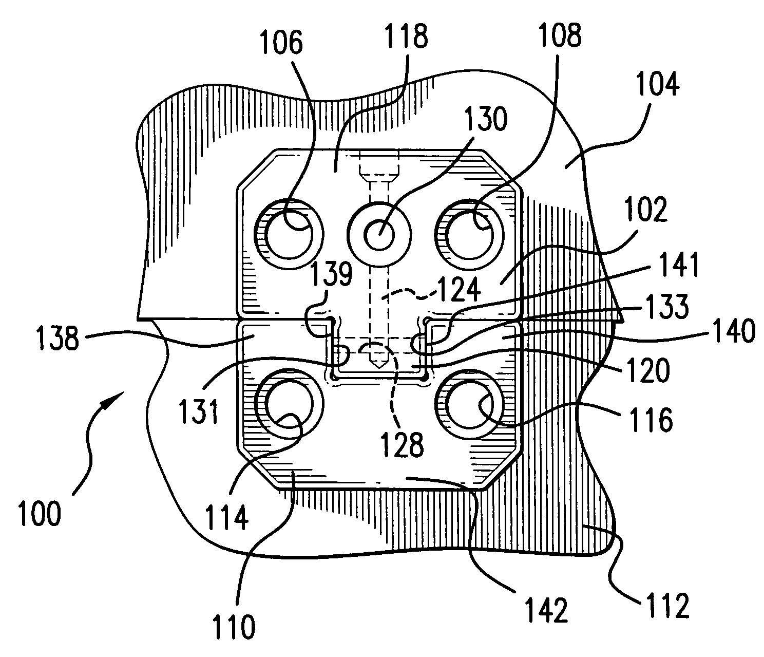
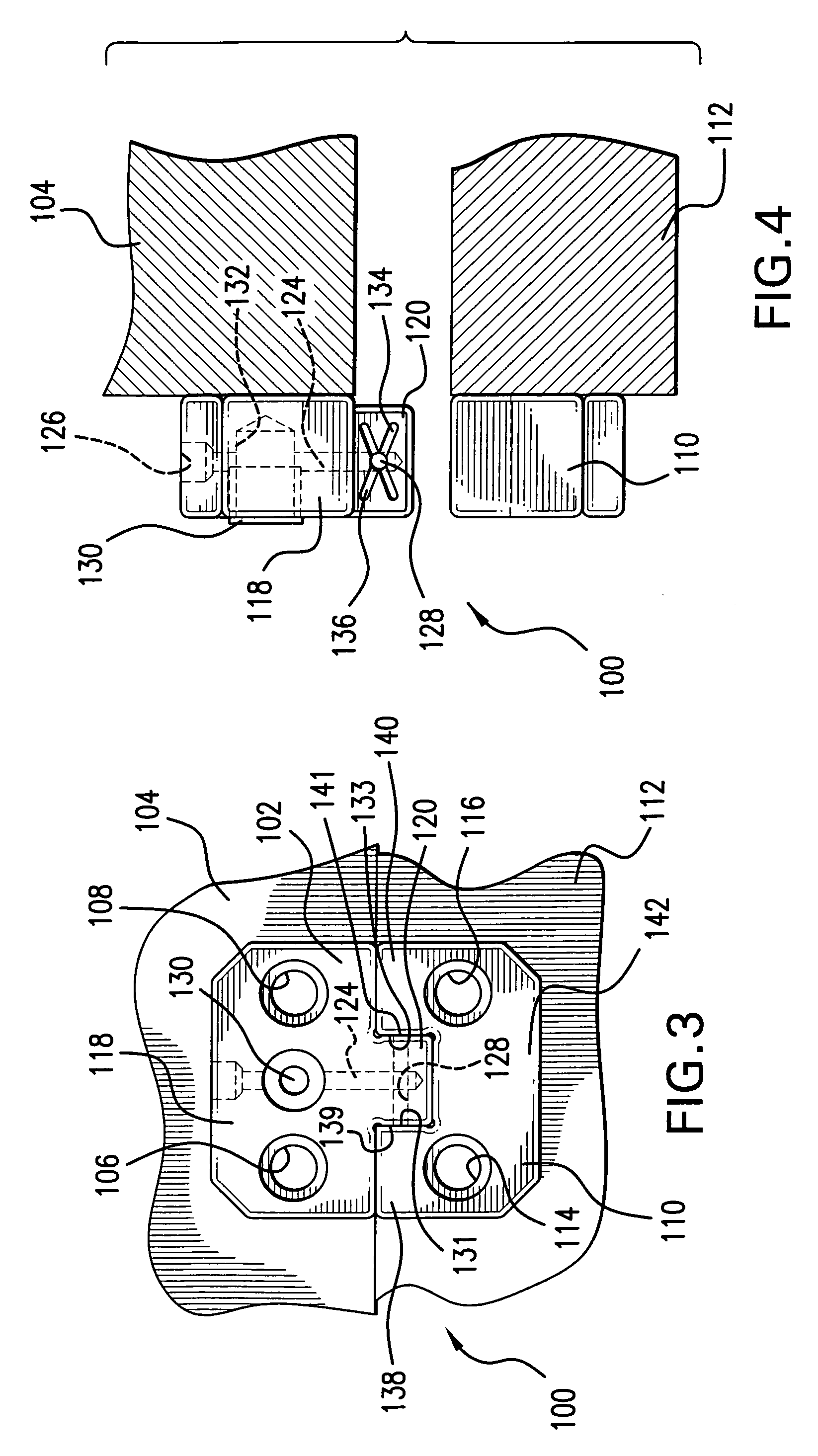
[0026]In order to maintain the mold halves in alignment, despite the considerable pressure exerted upon the mold halves, and the thermal differential between the first and second mold halves, which can approach 20° F., mold locks are employed on each side of the mold assembly 10. Mold locks 20, 22 are shown in FIG. 1 and additional mold locks (not shown) are e...


PUM

PropertyMeasurementUnit
Widthaaaaaaaaaa
Thermal propertiesaaaaaaaaaa

Abstract

A mold for maintaining alignment between mold halves despite a thermal differential between the mold halves. The lock comprises (1) a T-shaped member, consisting of an enlarged, rectangular head and a tongue extending therefrom, and (2) a receptacle with an outwardly opening U-shaped pocket to receive the tongue of the T-shaped member, when the mold halves are pressed together. A vertical conduit is formed in the head and tongue of the T-shaped member, and a horizontal channel, extending through the tongue, intersects the lower end of the conduit. At lest one groove is defined in each side wall of the conduit. A grease fitting is located in a blind hole in the head of the T-shaped member, so that lubricant flows through the vertical conduit, into the horizontal channel, and into the grooves in the opposite side walls of the tongue. The grooves are usually formed in pairs, and are configured in an intersecting X configuration. The midpoint of the X configuration corresponds to one end of the horizontal channel in the receptacle. The grease fitting, vertical conduit, horizontal channel, and grooves in the opposite side walls of the tongue deliver a film of lubricant into the limited clearances between the side walls of the tongue and the interior walls of the pocket to prevent metal-to-metal, line-to-line contact therebetween. In an alternative embodiment, the grooves are located in the parallel side walls of the U-shaped pocket, and are configured in an intersecting X configuration, to deliver the film of lubricant.

Description

[0001]The present invention pertains generally to mold locks for maintaining alignment between mold halves, and more particularly to grooves defined within the mold lock for supplying a lubricating film between contacting metal surfaces within the mold lock.BACKGROUND OF THE INVENTION[0002]Injection molds are used to form a variety of objects from plastic materials. The molds usually consist of two halves, which are aligned by leader pins and bushings. A die fits within a cavity defined between the two halves of the mold. A representative mold is shown in U.S. Pat. No. 5,662,946, to Steven D. Pratt et al; the first or fixed mold half 102 and the movable mold half 109 are shown in FIG. 1 of the Pratt et al patent. Leader pins 114, that fit into corresponding bushings 116, are also depicted, and side-locks 128, 129 assist in the alignment, and registration, of the two mold halves during molding.[0003]As the mold in Pratt et al closes, the initial alignment of the mold halves occurs as...

Claims


Application Information

Patent Timeline
IPC IPC(8): B29C45/83
CPCB29C45/2606B29C45/83
Inventor LEMKIN, JACK
Owner LEMKIN JACK
Why Eureka
Try Eureka