Display medium driving method

Inactive Publication Date: 2007-06-12
E INK CORPORATION
View PDF17 Cites 18 Cited by
  • Summary
  • Abstract
  • Description
  • Claims
  • Application Information

AI Technical Summary

Benefits of technology

[0033]With this drive method the drive voltage gradually rises to a peak maximum voltage. There is, therefore, no sharp change in the field when changing the picture, and unnecessary particle movement is suppressed. As a result, the absolute value of the particle drive start voltage can be increased and image contrast can be incre

Problems solved by technology

Of these display media, thermal rewritable image displays and liquid crystals capable of storing an image offer excellent image retention but suffer from low contrast between the image and non-image (background) areas because they cannot present a paper-white background.
It is therefore difficult to present a sharp image.
However, while these displays can present a clear white background, sufficient image density cannot be achieved due to the intrusion of the white fluid into the gaps between color particles in the image areas.
Sufficient contrast therefore cannot be achieved between the image and non-image areas.
A sharp image display therefore cannot be achieved.
Furthermore, if the display medium is bent when removed from the image display, there is the possibility of the white fluid leaking from the display medium.
However, this display medium cannot present a 100% white display in principle even if a field is applied to the display medium so that the entire display surface shows white because ambient light rays penetrating the gaps between the balls are not reflected and are lost inside the display medium.
It is also difficult to completely reverse the particles, leading to a drop in contrast and, as a result, making it difficult to present clear images.
The problem with this type of display medium is that contrast cannot be sufficiently improved because there is conductive color toner not in contact with the charge transport layer displayed t

Method used


Image

  • Display medium driving method
  • Display medium driving method
  • Display medium driving method

Examples


embodiments

[0118]The preferred embodiments of the present invention are described next below. It should be noted that unless otherwise stated “parts” as used below refers to “parts by weight.”

embodiment 1

[0131]Using the display medium prepared as described in comparison 1 above, a +500V rectangular wave voltage pulse is applied to the ITO electrode of the display substrate to turn the display substrate entirely white. A positive rectangular wave voltage pulse is then applied to the ITO electrodes of the display substrate for 25 msec, and immediately thereafter a negative rectangular wave voltage pulse of the same absolute value as the above positive rectangular wave voltage pulse is applied to the ITO electrodes of the display substrate for 25 msec. The voltage supply is then stopped and the image density on the display substrate is measured using a densitometer (X-Rite 404A, X-Rite Co.).

[0132]A +500V rectangular wave voltage pulse is then applied to the ITO electrodes of the display substrate to turn the entire display substrate white. The above procedure is then repeated while gradually increasing the absolute value of the voltage pulse.

[0133]A −500V rectangular wave voltage pulse...

embodiment 2

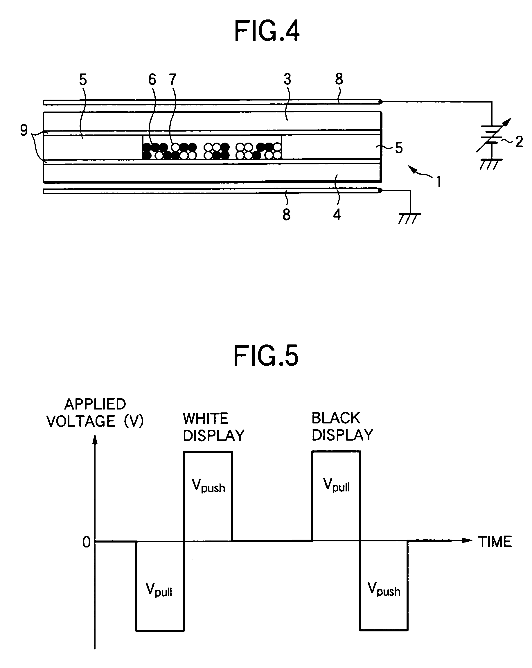
[0136]Using the display medium of embodiment 1 above, a +500V rectangular wave voltage pulse is applied to the ITO electrode of the display substrate to turn the display substrate entirely white. A +200V rectangular wave voltage pulse is then applied to the ITO electrodes of the display substrate for 25 msec, and immediately thereafter a −200V rectangular wave voltage pulse is applied to the ITO electrodes of the display substrate for 25 msec. The voltage supply is then stopped and the image density on the display substrate is measured using a densitometer (X-Rite 404A, X-Rite Co.). Applying the above pulse pair and density measurement are then repeated. The results are shown in FIG. 10.

[0137]As shown in FIG. 10, black image density gradually increases as the number of time the drive voltage pulse is applied to the display medium increases, and is substantially saturated after five times. Note that in FIG. 10 the density (1.0) obtained by applying a −200-V pulse only once for 25 mse...


PUM


Abstract

A drive method for a display medium containing two particle types can drive the display medium with a low voltage and thereby achieve high image resolution, downsize the drive circuit, and lower the cost while improving the durability of the display medium. The display medium has a pair of substrates, at least one of which is transparent, disposed with a gap therebetween, and two types of particles of different color and charge characteristics sealed between the pair of substrates. To change the displayed image, the drive method applies a voltage pulse to at least one of the pair of substrates to pull particles that are to move to the substrate to which the particles that are to move adhere, and then applies a voltage pulse to move the particles that are to move to the substrate opposite the substrate to which the particles that are to move adhere.

Description

BACKGROUND OF THE INVENTION[0001]1. Field of the Invention[0002]The present invention relates to a method for driving a display medium, and relates more particularly to a display medium driving method for applying a voltage pulse to a display medium containing two types of particles of different color and charge characteristics.[0003]2. Description of Related Art[0004]Twisting ball displays (dichroic twisting ball displays), electrophoretic image displays, magnetophoretic image displays, thermal rewritable image displays, and liquid crystals capable of storing an image have been proposed as display media capable of repeating image display.[0005]Of these display media, thermal rewritable image displays and liquid crystals capable of storing an image offer excellent image retention but suffer from low contrast between the image and non-image (background) areas because they cannot present a paper-white background. It is therefore difficult to present a sharp image.[0006]Furthermore, di...

Claims


Application Information

Patent Timeline
IPC IPC(8): G09G3/34G02F1/167
CPCG02F1/167G09G3/344G09G2300/06G09G2310/06G09G2310/066
Inventor MACHIDA, YOSHINORISHIGEHIRO, KIYOSHIYAMAGUCHI, YOSHIROSAKAMAKI, MOTOHIKOMATSUNAGA, TAKESHI
Owner E INK CORPORATION
Why Eureka
Try Eureka