Differentially-cured materials and process for forming same

a technology of differentially cured materials and process, applied in the direction of reflex reflectors, lighting and heating apparatus, instruments, etc., can solve problems such as discontinuity on the surface of the structur

Inactive Publication Date: 2007-06-12
ORAFOL AMERICAS
View PDF108 Cites 54 Cited by
  • Summary
  • Abstract
  • Description
  • Claims
  • Application Information

AI Technical Summary

Benefits of technology

[0015]The invention has many advantages including forming a permanent pattern in materials that is transparent and does not significantly detract from other functions while adding the benefits described below. The material can have the pattern act similar to a watermark in paper to provide a means of identification for a product's source that is difficult to forge. Also, the pattern can serve as a function of light management by altering the path of light that is transmitted through such a structure having the pattern.

Problems solved by technology

The first amount of time or rate is sufficiently different than the second amount of time or rate to result in a discontinuity on the surface of the structure.

Method used


Image

  • Differentially-cured materials and process for forming same
  • Differentially-cured materials and process for forming same
  • Differentially-cured materials and process for forming same

Examples


example 1

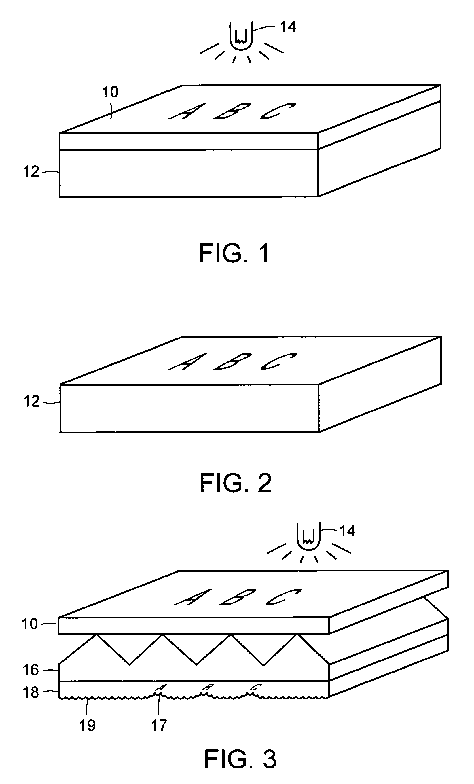
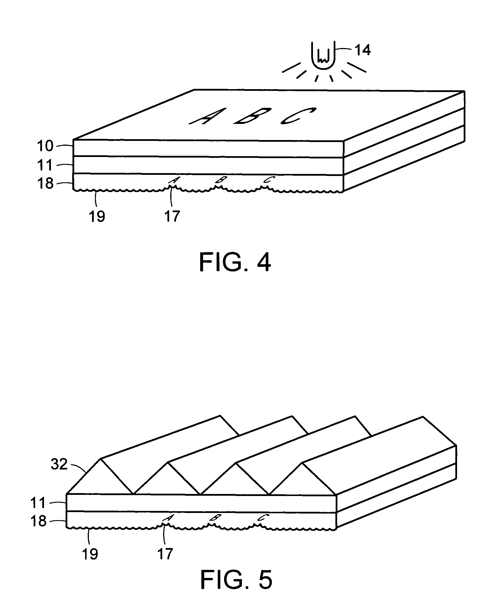
[0140]A polycarbonate substrate was covered with a number 30LC mask film (manufactured by Ivex Packaging Corporation) that had a blue colored “PEEL” pattern printed on it. Moth-eye structures were cast on the opposite side of the substrate and cured by ultraviolet radiation at a web speed of about twelve meters per minute (forty feet per minute) past two 157–236 watts / lineal centimeter (400–600 Watts / lineal inch) ultraviolet lamps manufactured by Eye Ultraviolet Corporation. After removing the mask film, the cured moth-eye structures retained the “PEEL” pattern that could not be readily seen at a zero degree viewing angle but were pronounced at about a fifteen degree viewing angle.

example 2

[0141]Alphanumeric images were handwritten onto the surface of a mask film on a cling mask sample of polycarbonate film manufactured by Rowland Technologies Incorporated. Commonly available felt tip marker pens were used to form the images. An ultraviolet curable coating of epoxy acrylate was applied to the other side of the polycarbonate film and cured under a 236 Watts per lineal centimeter (600 Watts per lineal inch) lamp at about 4.6 meters per minute (fifteen feet per minute). The mask film was removed and the cured coating was visually examined at various angles. The images that had been on the mask film were visible at shallow viewing angles in the cured coating.

example 3

[0142]FIG. 25 shows a plot of a surface profile with an interference microscope trace that was made across the surface of a film made with the pattern transfer process.

[0143]The height of the features is slightly less than one wavelength of red light. Red light wavelength is 632.8 nm (2.49×10⁻⁵ inches). The height of the features is approximately 500 to 900 nm (1.9685×10⁻⁵ to 3.5433×10⁻⁵ inches). The average height is about 640 nm (2.5197×10⁻⁵ inches).

[0144]The height and slope of the features caused some light deviation as the light passes through the film. However, the effect on LCD back light brightness appears to be positive by about a one percent gain. Additionally, these features can act as resting points for the prism peaks of collimating films as the films are stacked upon each other and therefore prevent the majority of the prism peaks from being damaged by abrasion.

[0145]FIG. 26 is similar to the embodiment of FIG. 13 and illustrates a visible random shaped surface that ca...


PUM

PropertyMeasurementUnit
angleaaaaaaaaaa
angleaaaaaaaaaa
included angleaaaaaaaaaa

Abstract

A light-redirecting optical structure includes a first side and a second side, the first side including plurality of linear prisms having a visibly random shaped surface on the prisms and a plurality of cross-cut prisms on first side which are oriented at an angle such that it is greater than zero degrees but less than 180 degrees.A backlight wedge includes a stepped structure on a bottom side that decreases in size traversing the wedge away from a light source which is positioned at an end and having a visibly random shaped surface on said wedge.

Description

RELATED APPLICATIONS[0001]This application is a Continuation-in-Part of U.S. patent application Ser. No. 10 / 744,916, filed on Dec. 23, 2003, which is a Continuation-in-Part of U.S. patent application Ser. No. 10 / 428,318, filed on May 2, 2003 now abandoned, which is a Continuation-in-Part of U.S. patent application Ser. No. 09 / 928,247, filed on Aug. 10, 2001, which claims the benefit of U.S. Provisional Application No. 60 / 226,697, filed on Aug. 18, 2000, and U.S. Provisional Application No. 60 / 256,176, filed on Dec. 15, 2000. The entire teachings of the above applications are incorporated herein by reference.BACKGROUND OF THE INVENTION[0002]Many retroreflective sheeting, collimating films, etc. are made to exacting dimensions in metal molds that are difficult and expensive to make. The metal molds can represent a significant barrier of entry into a high quality market for optical sheeting and films. However, knock-off manufacturers of retroreflective sheeting and collimating film can...

Claims


Application Information

Patent Timeline
Patent Type & Authority Patents(United States)
IPC IPC(8): G02B27/10B29C35/08B29C35/10B29D11/00G02B5/04G02B5/12G03F7/00
CPCB29C35/0894B29C35/10B29D11/00B29D11/00605G02B5/045G02B5/12G02B5/124G02B6/0053G03F7/001B29C2035/0827B29K2105/243B29K2995/003B29L2011/0083G02B6/0038G02B27/30
Inventor MULLEN, PATRICK W.NILSEN, ROBERT B.ROWLAND, WILLIAM P.
Owner ORAFOL AMERICAS
Why Eureka
Try Eureka