
Method and apparatus for dynamic placement of an integration window in a disk drive having a disk surface with spiral servo information written thereon

a technology of spiral servo information and integration window, which is applied in the field of data storage devices, can solve the problems of increasing the noise in the integration window, increasing the cost and time of stw, and so as to increase the dynamic range without increasing the size of the integration window

Inactive Publication Date: 2007-06-12
MAXTOR
View PDF10 Cites 51 Cited by
  • Summary
  • Abstract
  • Description
  • Claims
  • Application Information

AI Technical Summary

Benefits of technology

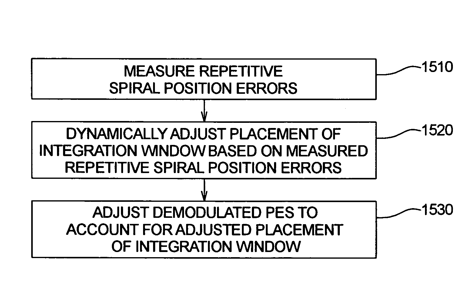
[0046]The present invention is directed to a method and apparatus for dynamic placement of an integration window in a disk drive having a disk surface with spiral servo information written thereon. In one embodiment, a read head is provided for reading the spiral servo information and generating a read signal envelope. A repetitive spiral position error, associated with one spiral of the spiral servo information, is measured. Placement of an integration window is dynamically adjusted based upon the measured repetitive spiral position error, so that a read signal envelope read by the read head appears more towards the center of the integration window than if the placement of the integration window was not dynamically adjusted. By adjusting the placement of the integration window, dynamic range is increased without increasing the size of the integration window.

Problems solved by technology

In general, a STW is a very expensive piece of capital equipment.
Even a small reduction in the amount of data needed to be written by the STW per disk surface can result in a significant cost and time savings.
However, if the size of the integration was increased, the amount of noise in the integration window would increase, because the position of the reader is determined by integrating over the entire integration window and then dividing by 2.

Method used


Image

  • Method and apparatus for dynamic placement of an integration window in a disk drive having a disk surface with spiral servo information written thereon
  • Method and apparatus for dynamic placement of an integration window in a disk drive having a disk surface with spiral servo information written thereon
  • Method and apparatus for dynamic placement of an integration window in a disk drive having a disk surface with spiral servo information written thereon

Examples


Embodiment Construction

[0067]While this invention is susceptible of embodiments in many different forms, there are shown in the drawings and will herein be described in detail, preferred embodiments of the invention with the understanding that the present disclosure is to be considered as an exemplification of the principles of the invention and is not intended to limit the broad aspects of the invention to the embodiments illustrated.

[0068]In one prior system, integration windows are opened at static times (or, equivalently, placed at static locations), which ignores potential repetitive spiral position errors (or repeatable runout (RRO)) resulting from misplacement of spirals by the STW. If spiral servo information were perfectly placed by the STW, then static integration windows would be very effective, because read signal envelopes read by a read head would be positioned in the center of their corresponding integration windows when there was no position error.

[0069]The present invention dynamically pl...


PUM


Abstract

The present invention is directed to a method and apparatus for dynamic placement of an integration window in a disk drive having a disk surface with spiral servo information written thereon. A read head is provided for reading the spiral servo information and generating a read signal envelope. A repetitive spiral position error, associated with one spiral of the spiral servo information, is measured. Placement of an integration window is dynamically adjusted based upon the measured repetitive spiral position error, so that a read signal envelope read by the read head appears more towards the center of the integration window than if the placement of the integration window was not dynamically adjusted. By adjusting the placement of the integration window, dynamic range is increased without increasing the size of the integration window.

Description

CROSS-REFERENCE TO RELATED APPLICATIONS[0001]Priority is claimed from U.S. Provisional Patent Application Ser. No. 60 / 475,050 filed Jun. 2, 2003, which is incorporated herein by reference in its entirety. Priority is also claimed from U.S. Provisional Patent Application Ser. No. 60 / 475,129 filed Jun. 2, 2003, which is also incorporated herein by reference in its entirety.FIELD OF THE INVENTION[0002]The present invention relates generally to data storage devices, such as disk drives. More particularly, the present invention relates to a method and apparatus for dynamic placement of an integration window in a disk drive having a disk surface with spiral servo information written thereon.BACKGROUND OF THE INVENTION[0003]Computer disk drives store information on magnetic disks. Typically, the information is stored on each disk in concentric tracks that are divided into sectors. Information is written to and read from a disk by a transducer that is mounted on an actuator arm capable of m...

Claims


Application Information

Patent Timeline
IPC IPC(8): G11B21/02G11B5/596
CPCG11B5/59611G11B5/59661
Inventor RAY, BILLVANLAANEN, JOHNLIIKANEN, BRUCE
Owner MAXTOR
Learn More