Method and apparatus for impulse radio transceiver calibration

a radio transceiver and impulse technology, applied in the direction of amplitude demodulation, instruments, using reradiation, etc., can solve the problems of global positioning system, high-complex system of determining the position of objects, and waiting more than 100 minutes

Active Publication Date: 2007-06-12
HUMATICS CORP
View PDF11 Cites 127 Cited by
  • Summary
  • Abstract
  • Description
  • Claims
  • Application Information

AI Technical Summary

Benefits of technology

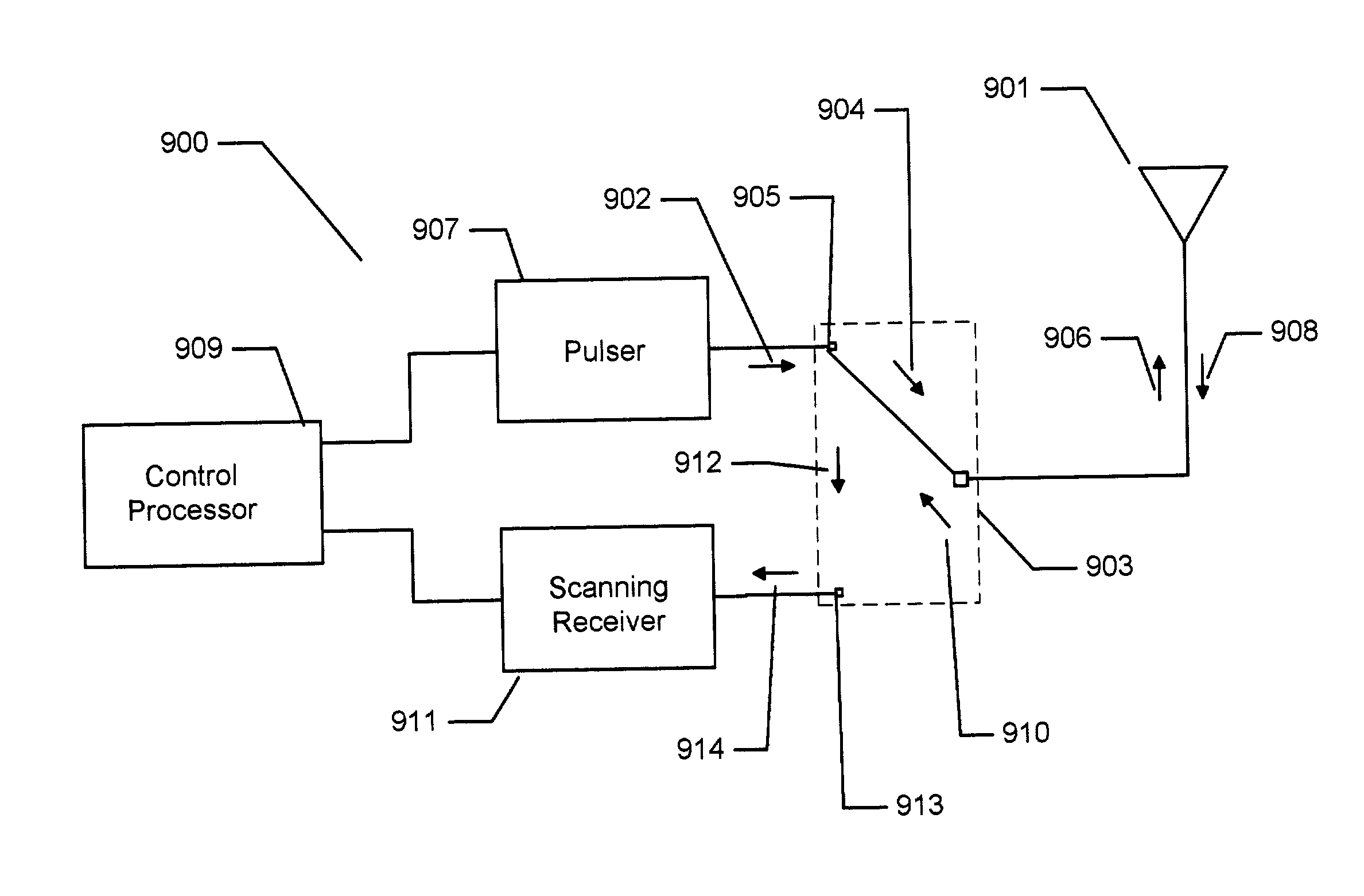
[0013]A system using the above-described method comprises a control processor for timing functions and cal

Problems solved by technology

The global positioning system (GPS) operated by the United States Department of Defense, for example, is a highly complex system of determining the position of an object.
The system usually requires two passes of the satellite, necessitating a wait of more than 100 minutes.
Although the TRANSIT system is capable of high accuracy (on the order of one meter), the delay required is unacceptable for commercial applications.
Although these systems accurately determine the unknown position of an object, they are extremely complex, and, more importantly, expensive to implement.
Also, response times of GPS and TRANSIT systems are typically slow due to their narrow bandwidth.
Furthermore, since these systems depend on orbiting satellites, they require an unimpeded view of the sky to operate effectively.
However, it is difficult to identify one or more containers among hundreds, or thousands of containers in a terminal.
Similar problems are also encountered in airports and railway terminals where containers are kept in storage sites.
However, usi

Method used


Image

  • Method and apparatus for impulse radio transceiver calibration
  • Method and apparatus for impulse radio transceiver calibration
  • Method and apparatus for impulse radio transceiver calibration

Examples


Embodiment Construction

Overview of the Invention

[0042]The present invention will now be described more fully in detail with reference to the accompanying drawings, in which the preferred embodiments of the invention are shown. This invention should not, however, be construed as limited to the embodiments set forth herein; rather, they are provided so that this disclosure will be thorough and complete and will fully convey the scope of the invention to those skilled in art. Like numbers refer to like elements throughout.

[0043]Impulse Radio Technology Overview

[0044]Recent advances in communications technology have enabled ultra wideband technology (UWB) or impulse radio communications systems “impulse radio”. To better understand the benefits of impulse radio to the present invention, the following review of impulse radio follows. Impulse radio has been described in a series of patents, including U.S. Pat. No. 4,641,317 (issued Feb. 3, 1987), U.S. Pat. No. 4,813,057 (issued Mar. 14, 1989), U.S. Pat. No. 4,9...


PUM


Abstract

A method for calibrating an impulse radio distance measuring system comprising an impulse radio transceiver by conducting a pulse through a transmit receive switch to an antenna, receiving return energy which has been discharged across the transmit receive switch, determining a time of arrival of the return energy. The return energy is comprised of two distinct pulses, one of which represents discharge of the transmit switch as the original pulse travels to the antenna, the second represents energy reflected from the antenna and again discharged across the transmit receive switch while the switch is in the transmit position. The timing of the un-reflected energy is determined then the timing of the reflected energy relative to the un-reflected energy is determined through auto-correlation of the time domain scan of the received composite waveforms.

Description

CROSS-REFERENCE TO RELATED APPLICATIONS[0001]Priority to Provisional Application Ser. No. 60 / 322,689, filed Sep. 17, 2001, is hereby claimed.BACKGROUND[0002]In recent years, modern communications technology has provided various systems for position determination. The global positioning system (GPS) operated by the United States Department of Defense, for example, is a highly complex system of determining the position of an object. The GPS system depends on measuring the time-of-flight of microwave signals from three or more orbiting satellite transmitters by a navigation receiver that computes the position of the mobile unit. According to the GPS system, each satellite broadcasts a time-stamped signal that includes the satellite's ephemeris, i.e., its own position. When the mobile unit receives a GPS signal, the mobile unit measures the transmission delay relative to its own clock and determines the pseudo-range to the transmitting satellite's position. The GPS system requires three...

Claims


Application Information

Patent Timeline
IPC IPC(8): H04B1/38H04L5/16G01S13/02
CPCG01S13/0209G01S13/76
Inventor LANGFORD, DAVID W.TROUTMAN, DENNIS L.
Owner HUMATICS CORP
Why Eureka
Try Eureka