Plastic spout

Inactive Publication Date: 2007-06-19
SHOWA MARUTSUTSU CO LTD
View PDF16 Cites 22 Cited by
  • Summary
  • Abstract
  • Description
  • Claims
  • Application Information

AI Technical Summary

Benefits of technology

[0011]It is an object of the present invention, according to a first aspect thereof, to provide a spout which can be sealed in place w

Problems solved by technology

This is because the heat which is supplied during sealing cannot be dissipated to

Method used


Image

  • Plastic spout
  • Plastic spout
  • Plastic spout

Examples


Embodiment Construction

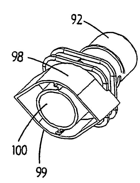
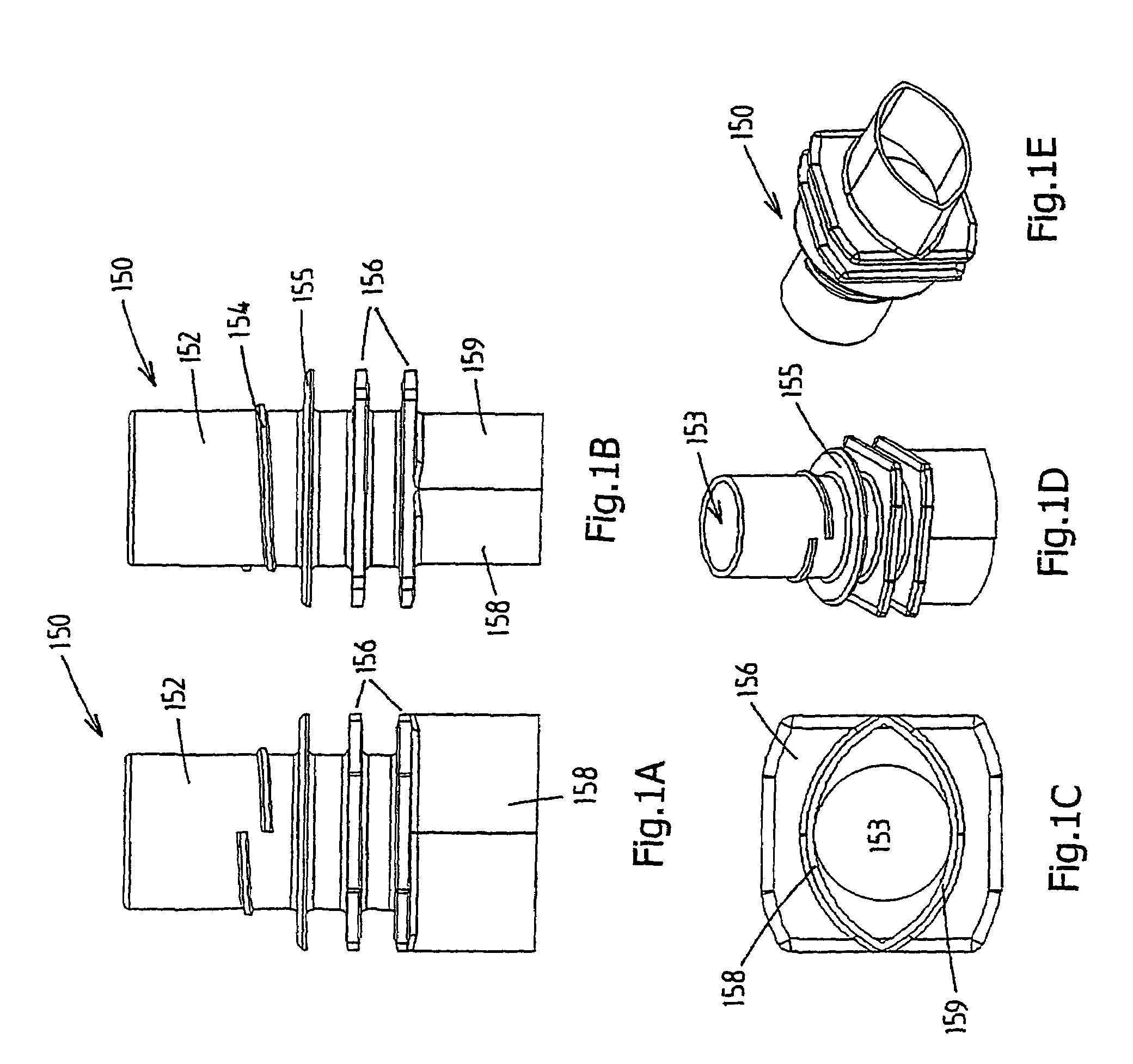
[0047]FIGS. 1a–e show a spout 150 which is produced by injection-moulding from a suitable plastic material and which is intended to be sealed between two foil walls of a pouch.

[0048]The spout 150 has a single-part spout body with, on the top side, an outwardly projecting tubular part 152 which forms a passage 153 for delivering a medium from the pouch and / or feeding a medium to the pouch.

[0049]The tubular part 152 is provided with a screw thread 154 for a screw cap (not shown), which can be used to close off the spout 150.

[0050]The outwardly projecting tubular part 152 is furthermore provided with a locking flange 155 for the screw cap and, beneath this, two circumferential flanges 156 which are used for handling means for the spout 150 and the pouch to engage on after the spout 150 has been sealed in the pouch.

[0051]On the underside, the spout 150 is provided with two sealing walls 158, 159 which project freely downwards, adjoin one another at their diametrically opposite ends and ...


PUM

PropertyMeasurementUnit
Lengthaaaaaaaaaa
Flexibilityaaaaaaaaaa

Abstract

A plastic spout 150,170 which is adapted to be sealed between two foil walls of a pouch. The spout has a spout body, which forms a passage 153 for delivering a medium from the pouch and/or feeding a medium to the pouch. In a bottom part thereof, the spout, on opposite sides, forms a sealing zone for a sealed connection to an adjoining foil wall. The sealing zones of the spout body are formed by sealing walls 158,159 which project downward from the spout body, each having a curvature over their entire length, such that each sealing wall is outwardly convex over its entire length with respect to an imaginary plane passing through the outermost ends, which adjoin one another, of the sealing walls. The sealing walls can preferably move flexibly transversely with respect to their plane and, on their inner side, are unsupported or are supported by one or more flexible supporting parts of the spout body.

Description

CROSS-REFERENCE TO RELATED APPLICATIONS[0001]This application is the national stage filing under 35 U.S.C. §371 of PCT / NL02 / 00646, filed Oct. 10, 2002, which claims priority to NL 1019161, filed Oct. 11, 2001 which is incorporated herein by reference.FIELD OF THE INVENTION[0002]The present invention relates to a plastic spout which is intended to be sealed between two foil walls of a pouch, comprising a spout body which forms a passage for delivering a medium from the pouch and / or feeding a medium to the pouch, which spout body, on opposite sides, forms a sealing zone for sealed connection to the adjoining foil wall.[0003]The present invention also relates to a method for sealing a plastic spout between two foil layers of a pouch.BACKGROUND OF THE INVENTION[0004]WO 00 / 66448, in particular FIGS. 9a–d, in the name of the present applicant has disclosed a plastic spout, which is adapted to be sealed between two foil walls of a pouch. The known spout has a spout body with a central tubu...

Claims


Application Information

Patent Timeline
IPC IPC(8): B65D35/00B65D33/38B65D75/58B65D77/30
CPCB65D75/5883B65D25/48Y10S383/906B65D2575/583
Inventor LAST, LAURENS
Owner SHOWA MARUTSUTSU CO LTD
Why Eureka
Try Eureka