Method and device for adapting the seat row arrangement in passenger planes according to need

a seat row arrangement and passenger plane technology, applied in the field of passenger plane seat row arrangement adapting methods and devices, can solve the problems of high personnel and time expenditure, high conversion cost, and inability to use seat row arrangement with rigid division into business class and economy class in an economically favorable manner

Inactive Publication Date: 2007-06-19
BISHOP
View PDF12 Cites 20 Cited by
  • Summary
  • Abstract
  • Description
  • Claims
  • Application Information

AI Technical Summary

Benefits of technology

[0008]One aspect of the present invention relates to a method in which an adaptation of the seat row arrangement in passenger planes is possible without a substantial increase in the standing time on the ground between two flights.
[0009]According to an embodiment of the present invention, a control device is stored with the desired seat row arrangement which is optimum for a particular flight. The control device then automatically moves the seat rows on their fastening rails, so that each seat row is moved to the position predetermined by the currently desired seat row arrangement. In particular, the control device is capable of generating control signals for each seat row whose position is to be changed in order to obtain the currently desired seat row arrangement, which control signals bring about the automatic release of the locking of the particular seat row on its fastening rails. The control signals may also control the operation of driving devices in such a manner that the seat row is moved continuously on the fastening rails to the position predetermined by the currently desired seat row arrangement. Further, actuation of a closure device automatically brings about the re-locking of the seat row in the predetermined position on its fastening rails. The control signals may also be implemented simultaneously for a plurality of seat rows.
[0010]This makes it possible for a passenger plane to obtain the data concerning the current passenger distribution and the resultant, optimum seat row arrangement for the next flight, preferably before it lands, so that, after it lands, it can be prepared in the shortest possible time for the next flight. If a change in the number of seat rows is necessary, for example, a few seat rows less is required, then, after removal of the excess seat rows, the control device, which is supplied with the data about the new desired seat row arrangement, on command can move those seat rows, which are to be displaced, automatically and individually under remote control and can re-lock them in the new desired position. If the number of seat rows in Business Class is significantly increased, it may be necessary to remove one or more seat rows from Economy Class; conversely, if the proportion of Business Class seat rows is reduced, it may be desirable to add a few Economy Class seat rows. This operation has to be carried out by the ground staff who receive, in good time before the plane arrives, as soon as the desired seat row distribution on the basis of the passenger occupancy is established, a message from the logistics center of the airline to provide, in the parked position of the plane, a required number of seat rows and to provide staff to remove or add seat rows.
[0013]This adaptation of the seat row arrangement can be carried out on the ground in a very short time without there being a significant increase in the standing time of the plane on the ground. The present invention therefore enables better use of the cabin space of the passenger planes to be obtained by the optimum division into Economy Class and Business Class seat rows being set in each case. Moreover, if a flight is not entirely full and after a few seat rows have been removed, the seat row distance for all of the seat rows can be increased, which improves the seating comfort for all passengers.
[0016]With embodiments of the present invention, it is also possible for the airlines to offer individual travelers who require it an increased distance from the seat row situated in front. This may be desirable, for example, as a service for increased comfort or as a safety measure for people at risk (risk of thrombosis on long-haul flights).
[0017]Furthermore, embodiments of the present invention enable the holding ready of replacement planes for the airlines to be realized more effectively, since, on the one hand, a plane of one type can be set to different passenger capacities and can thus, in principle, replace various other types of plane, as a result of which fewer types of plane have to be held ready as replacement planes. On the other hand, it is possible, in the event of a plane breaking down, for a number of following flights provided in accordance with the schedule to be set to increased capacity and for the passengers of the broken-down plane to be distributed to these following flights.

Problems solved by technology

Up to now, such changes in the seat row arrangement have been brought about only under exceptional circumstances, since they require a high expenditure in terms of personnel and time because each seat row whose position is to be changed has to be mechanically released from its fastening on the fastening rails, manually displaced and re-fastened by the ground staff.
It is clear that such conversions entail such high expenditure in terms of personnel and time that they are carried out only in exceptional circumstances.
On the other hand, in the case of the air traffic conditions nowadays when a passenger plane lands at an airport and, after the shortest possible standing time on the ground, sets off again on the return flight to the initial airport or to another airport, situations often arise in which the seat row arrangements with their rigid division into Business Class and Economy Class cannot be used in an economically favorable manner.
In this case, if a relatively large section of seat rows is held ready for Business Class, under flight conditions with a high proportion of economy passengers, the conveying capacity of the plane is not optimally used; on the other hand, at the peak times of Business Class use sufficient seat rows are not available in Business Class.

Method used


Image

  • Method and device for adapting the seat row arrangement in passenger planes according to need
  • Method and device for adapting the seat row arrangement in passenger planes according to need
  • Method and device for adapting the seat row arrangement in passenger planes according to need

Examples


Embodiment Construction

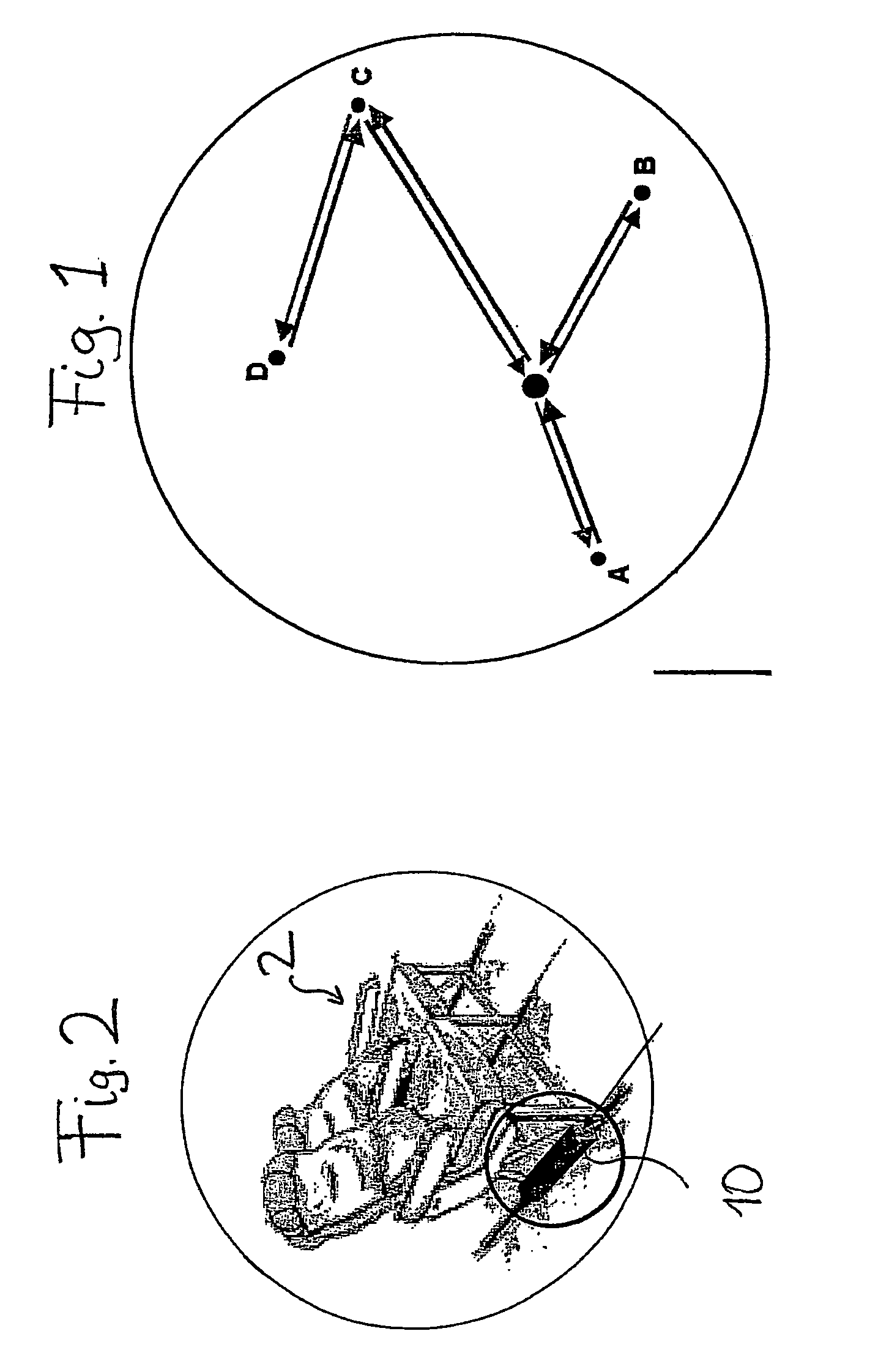
[0030]FIG. 1 shows a schematic illustration of flight routes between a central hub and destination airports A, B, C and D. By way of example, the starting point here will be a passenger plane whose normal configuration has 30 seats in Business Class and 90 seats in Economy Class. If the current requirements of the connection between the hub and the destination airport A are now considered, it may be the case that, in fact, for the flight from the hub to the destination airport A, 28 Business Class seats and 60 Economy Class seats are required whereas, on the return flight from A to the hub, 35 Business Class seats and 68 Economy Class seats are required. On the other hand, on the connection between the airports C and D, 21 Business Class seats and 60 Economy Class seats may be required. It can readily be seen that, with a standard configuration of the seat row arrangement with a fixed number of Business Class seats and Economy Class seats, an efficient use of the existing cabin spac...


PUM


Abstract

To allow for optimum arrangement of the rows of seats for any individual flight, the distance between rows is adjusted in the longitudinal direction of the passenger plane, optionally according to sections, by storing in a control device an actually desired arrangement of rows, and automatically displacing (via the control device) every row whose position has to be changed to achieve the actually desired arrangement of rows on its fastening rails to the position determined by the actually desired arrangement of rows. In this way, it is possible to provide a passenger plane, preferably prior to landing, with the data of the actual passenger distribution and the resulting optimum arrangement of rows for the next flight so that it can be prepared after landing for the next flight in the shortest possible time.

Description

CROSS-REFERENCES TO RELATED APPLICATIONS[0001]This application claims the benefit of PCT application no. PCT / EP03 / 01386 A1, filed 12 Feb. 2003, which in turn claims priority to German application no. 102 11 437.4 filed 5 Mar. 2002, each incorporated herein by reference in its entirety.STATEMENT REGARDING FEDERALLY SPONSORED RESEARCH OR DEVELOPMENT[0002]None.BACKGROUND OF THE INVENTION[0003]The present invention relates to a method and apparatus for adapting the seat row arrangement in passenger planes according to need.[0004]In passenger planes, the seat rows are mounted fixedly on fastening rails, which run in the floor in the longitudinal direction of the plane. The plane operator selects a seat row arrangement which is most favorable for the desired intended purpose. Seat row arrangement is understood here as being the number of seat rows and their distances from one another, which may be different in different sections in the longitudinal direction of the plane. As a rule, at t...

Claims


Application Information

Patent Timeline
Patent Type & Authority Patents(United States)
IPC IPC(8): B64D11/06B60N2/06B60N2/015
CPCB60N2/01575B64D11/06B64D11/0696
Inventor BISHOP, PETERMADOUI, NOUREDDINE
Owner BISHOP
Why Eureka
Try Eureka