Fitting for formation of a fluid-conducting connection

Active Publication Date: 2007-06-19
HYDAC FILTERTECHNIK GMBH
View PDF8 Cites 10 Cited by
  • Summary
  • Abstract
  • Description
  • Claims
  • Application Information

AI Technical Summary

Benefits of technology

[0006]According to the present invention, this object is attained by a fitting having a connecting element enclosing the opening in the container and embedded in the plastic of the wall of the container. A reinforcing element is provided with fastening means for mounting of the connecting element. The loads acting on the connection, such as fastening force, sealing force, dynamic (vibration) and thermal effects, do not act directly on the plastic material of the container wall. Rather, such loads act on the connecting element forming a reinforcing element. Embedding of a connecting element, which is made of an appropriately selected material with the operating loads taken into account, preferably metal or a duroplastic of high fatigue strength and thermal stability, affords reliable protection from deformation of the plastic material of the container wall, so that a connection reliable in operation and free of leaks is ensured.
[0009]An especially close connection of annular element and the plastic wall of the container is obtained if the side of the annular element facing the inside of the container has a plurality of pouch-like recesses. If the annular element is molded as an inserted element in rotomolding of the container, the plastic material entering the pouch-like recesses forms a serration of the annular element with the container wall and provides correspondingly good securing of the annular element against loads.

Problems solved by technology

The advantages of corrosion resistance, low weight, and ease of molding are offset in the case of plastic tanks, however, by the disadvantage that production of fluid-conducting connections on openings in the plastic wall of the container or tank has certain difficulties.
Because of the physical properties of the plastic material, the danger exists that deformations may occur in the area of the opening as a result of sealing forces and temperature effects.
Such deformations can lead to leaking between plastic tanks and add-on elements, even if costly sealing elements are employed.

Method used


Image

  • Fitting for formation of a fluid-conducting connection
  • Fitting for formation of a fluid-conducting connection
  • Fitting for formation of a fluid-conducting connection

Examples


Embodiment Construction

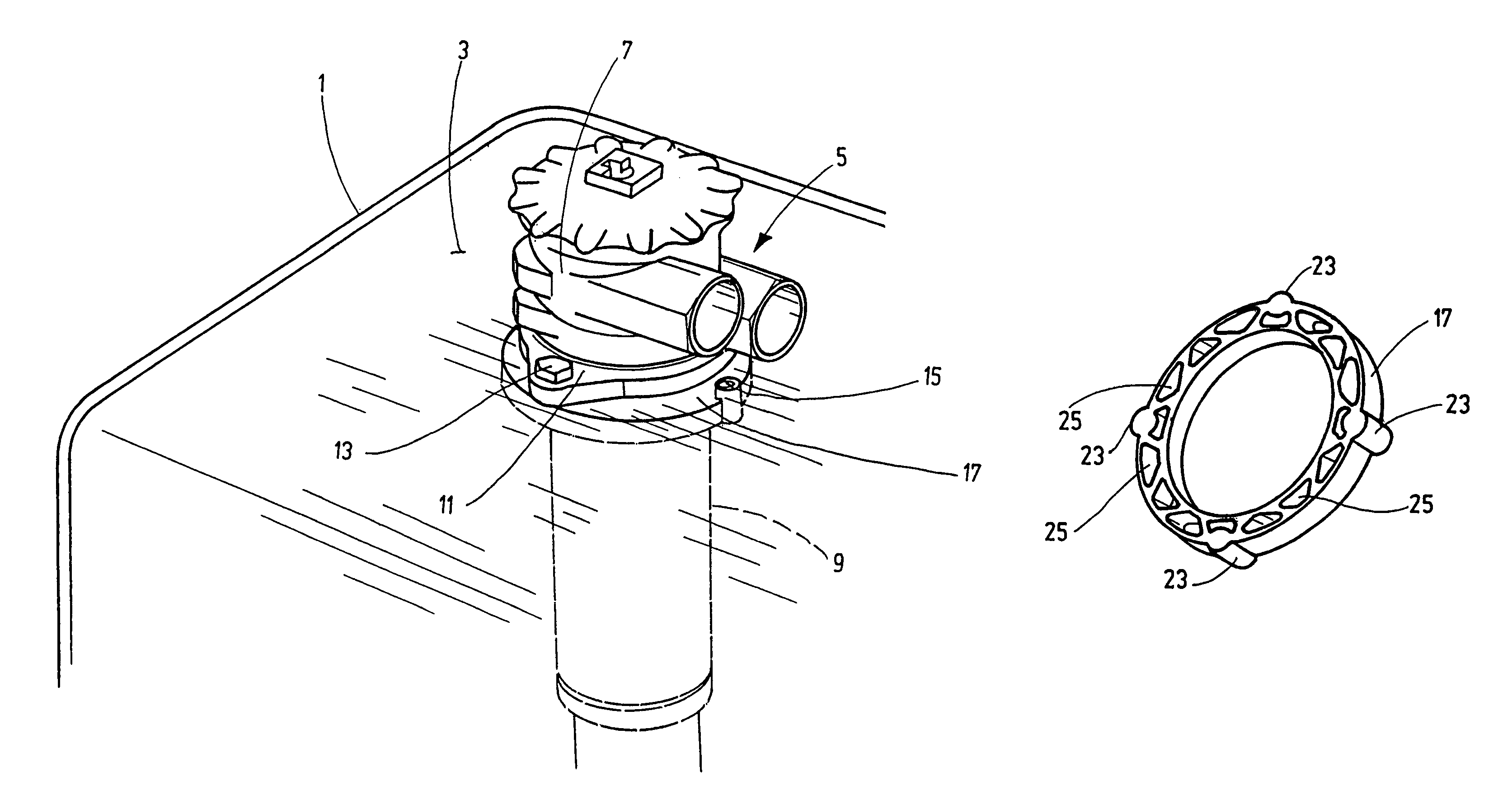
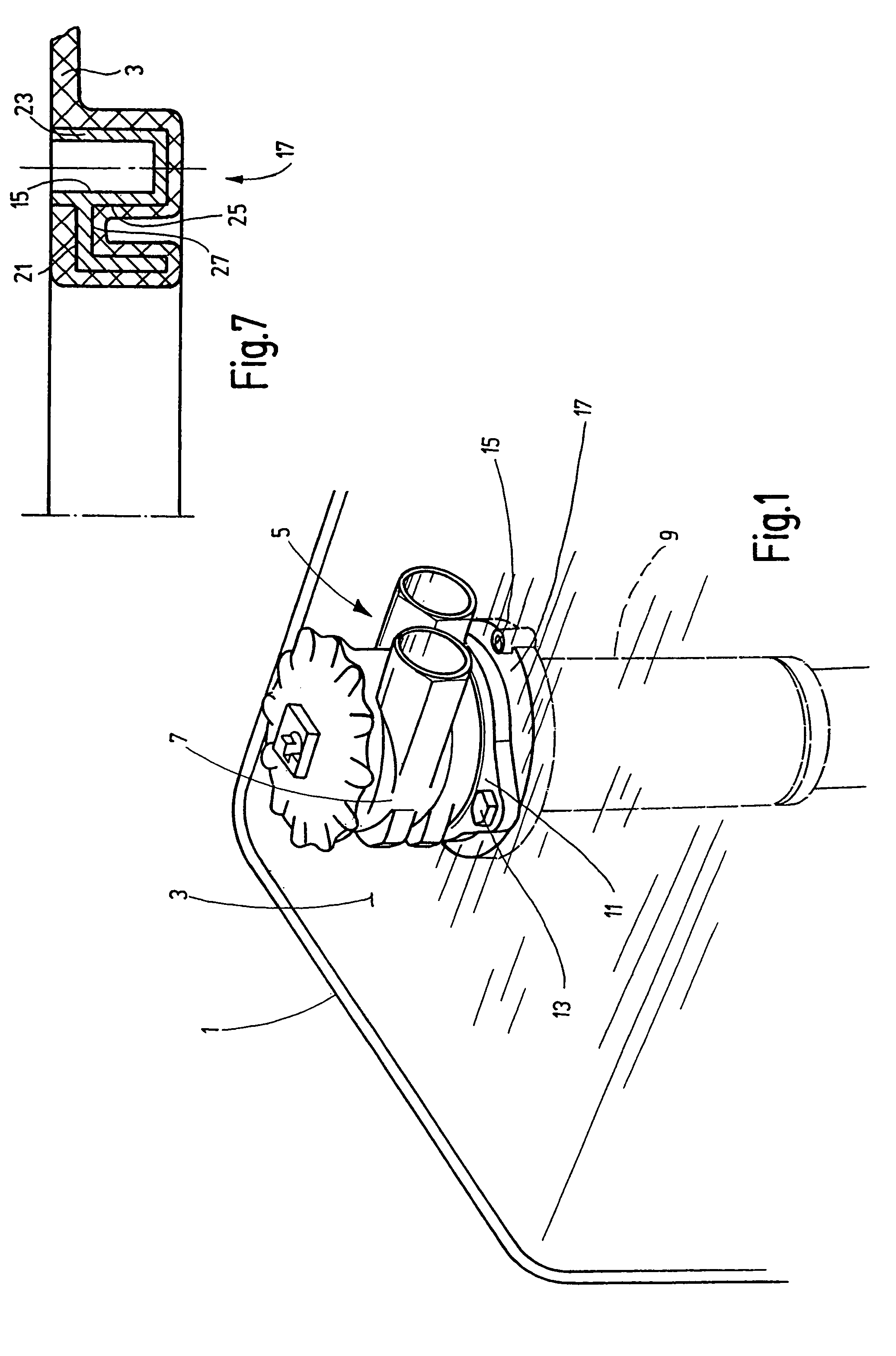
[0020]FIG. 1 illustrates a part of the upper side of a container in the form of a plastic tank 1 made of a plastic material suitable for larger containers by the known rotomolding process (cf. Schaab / Stoeckhert, AKunststoff Maschinenführer@ [Plastic Machine Operator]), pages 561–564). A tank opening is formed on the upper side in the rotomolding process. In the opening in the plastic wall 3, a fitting 5 is provided for a fluid-conducting, leak-free connection to a connecting element represented in the embodiment illustrated by the connecting head 7 of a tank-top filter the filter element 9 projecting through the opening to the interior of the tank 1. The connecting head 7 has a fastening flange 11 mounted on the tank 1 by two retaining screws 13, only one of which is visible in FIG. 1.

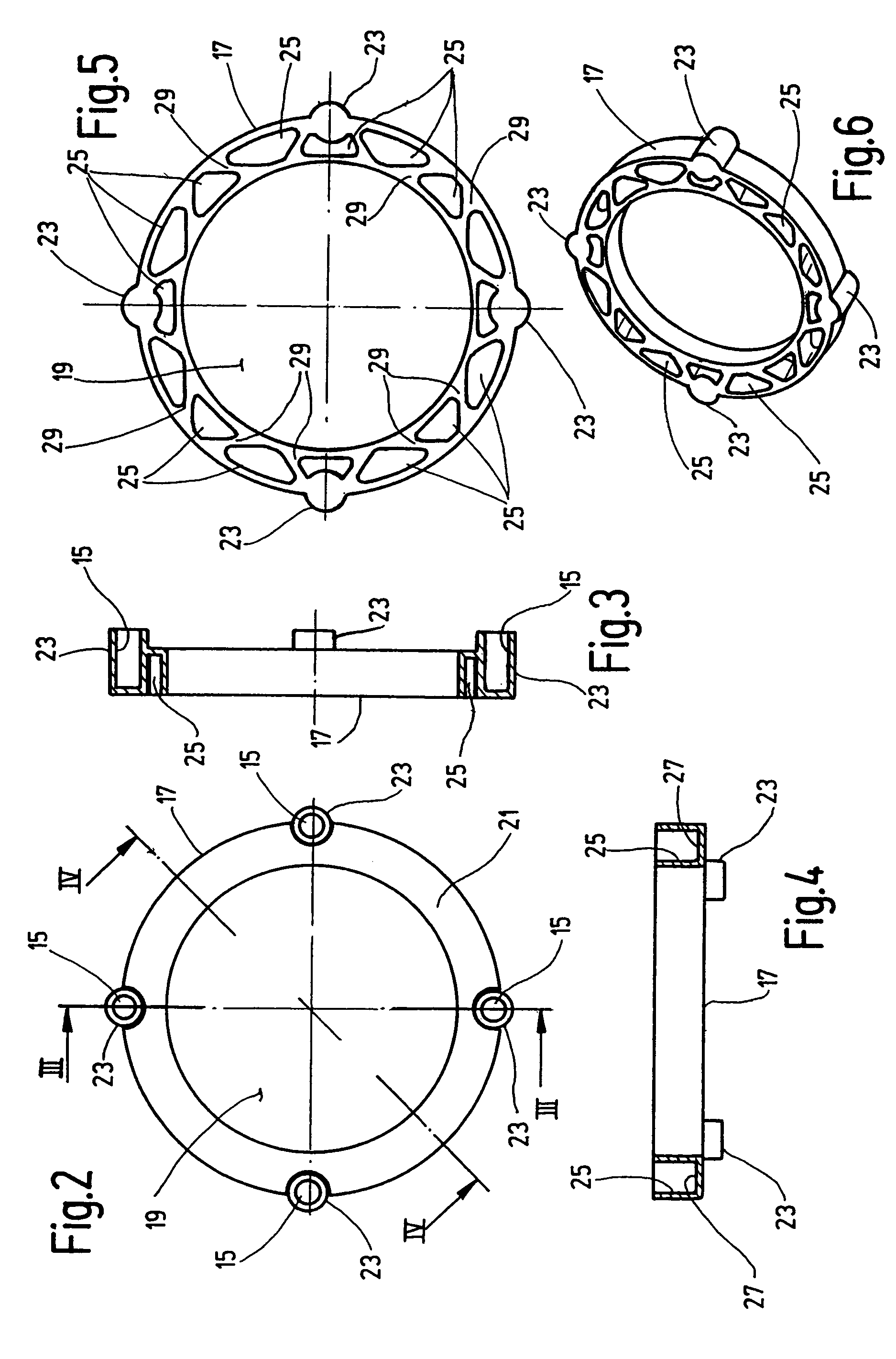
[0021]The retaining screws 13 extend through the fastening flange 11, and are screwed into internally threaded blind-end bores 15 provided on a connecting element configured as an annular element 17, a...


PUM


Abstract

A fitting 5 forms of a fluid-conducting connection in an opening in a plastic wall 3 of a container 1, a tank in particular, for receiving a fluid, a hydraulic fluid in particular. The fitting has a connecting element 17 embedded on the edge of the opening in the plastic of the wall 3 of the container and provided with fasteners 15 accessible from the exterior of the container 1 by which a connection part 11 of the fitting 5 may be mounted on the connecting element 17.

Description

FIELD OF THE INVENTION[0001]The present invention relates to a fitting for forming of a fluid-conducting connection on an opening in the wall of a container of plastic, in particular a tank for receiving a fluid, a hydraulic fluid in particular.BACKGROUND OF THE INVENTION[0002]Plastic tanks are widely used in hydraulic systems to contain hydraulic fluids. Because of the possibility of relatively simple configuration, low weight, and corrosion resistance, plastic tanks are extensively used especially in hydraulic systems of machines such as excavators, wheel loaders, and the like.[0003]Such tanks are usually produced by well-known rotomolding or blow molding processes. Polyethylene or polyamide plastics, for example, are used for larger containers such as tanks for hydraulic fluids.[0004]The advantages of corrosion resistance, low weight, and ease of molding are offset in the case of plastic tanks, however, by the disadvantage that production of fluid-conducting connections on openin...

Claims


Application Information

Patent Timeline
IPC IPC(8): F16L5/00B65D77/06F16L41/02
CPCF16L41/02F16L41/08
Inventor WILKENDORF, WERNER
Owner HYDAC FILTERTECHNIK GMBH
Why Eureka
Try Eureka