Trim press, article ejecting device, trim press article ejector, and method of stacking and cleaning out thermoformed articles

a technology of article ejector and trim press, which is applied in the direction of dough shaping, manufacturing tools, food shaping, etc., can solve the problems and affecting the efficiency of high-speed operation. , to achieve the effect of limiting the overall operating speed and performance, and reducing the sudden change of the direction of the kinematic components

Active Publication Date: 2007-06-19
IRWIN JERE F
View PDF8 Cites 3 Cited by
  • Summary
  • Abstract
  • Description
  • Claims
  • Application Information

AI Technical Summary

Benefits of technology

[0013]An article ejector is provided having kinematic linkages that drive ejector paddle assemblies in an article ejector mode, as well as a die cleaning mode where the kinematic linkages are driven via rotary motion in a continuous clockwise direction, in both modes, without having to impart changes in direction for the rotary drive mechanisms, and while maintaining maximum mechanical advantage of the kinematic linkages.
[0018]One advantage is to reduce sudden changes in direction of kinematic components on an article ejector for a trim press which will impart undesirable inertial forces to the machine that can limit overall operating speed and performance.
[0019]Another advantage is to provide continuously rotating kinematic components that have a mass that is configured to store energy as a fly wheel such that rotation of the kinematic linkages does not oscillate between clockwise and counter-clockwise directions.

Problems solved by technology

Such increases in operating speed can lead to significant increases in throughput and article output.
However, increases in operating speed have caused some problems in that a vacuum is created when drawing apart platens of a trim press which can actually suck severed articles or scrap web material back up into the trim press dies, which can create a jam or problem when running the trim press at relatively high operating speeds.
Secondly, the clockwise and counter-clockwise reciprocating motion of the kinematic linkages in servo motor 262 is not efficient or optimal for high-speed operation.
The associated moments of inertia are undesirable for relatively high operating speeds because the associated masses of the kinematic components suddenly change (or reverse) direction at high speed, which is undesirable and creates imbalance forces and increasing loading at component connections.

Method used


Image

  • Trim press, article ejecting device, trim press article ejector, and method of stacking and cleaning out thermoformed articles
  • Trim press, article ejecting device, trim press article ejector, and method of stacking and cleaning out thermoformed articles
  • Trim press, article ejecting device, trim press article ejector, and method of stacking and cleaning out thermoformed articles

Examples


Embodiment Construction

[0032]This disclosure of the invention is submitted in furtherance of the constitutional purposes of the U.S. Patent Laws “to promote the progress of science and useful arts” (Article 1, Section 8).

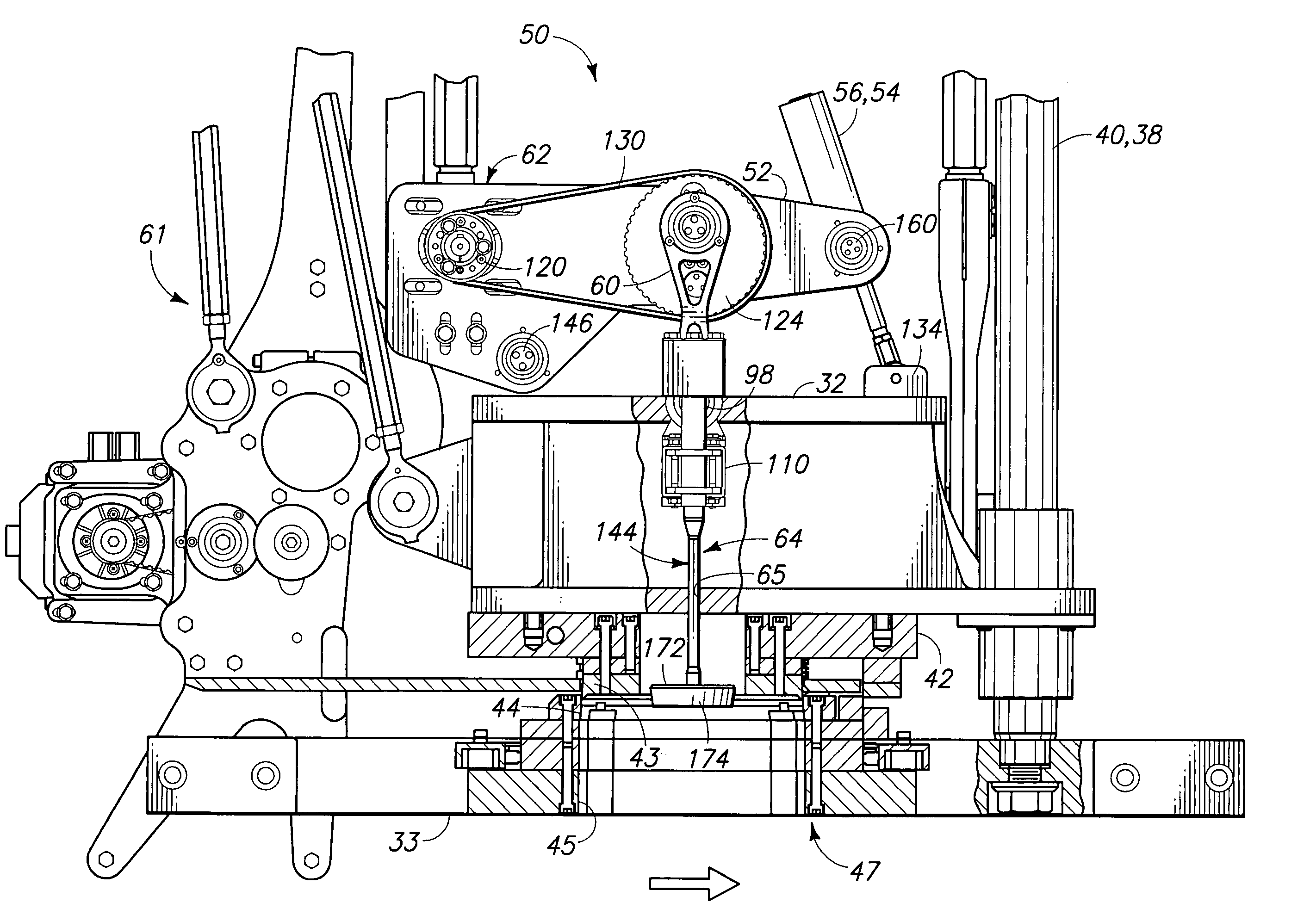
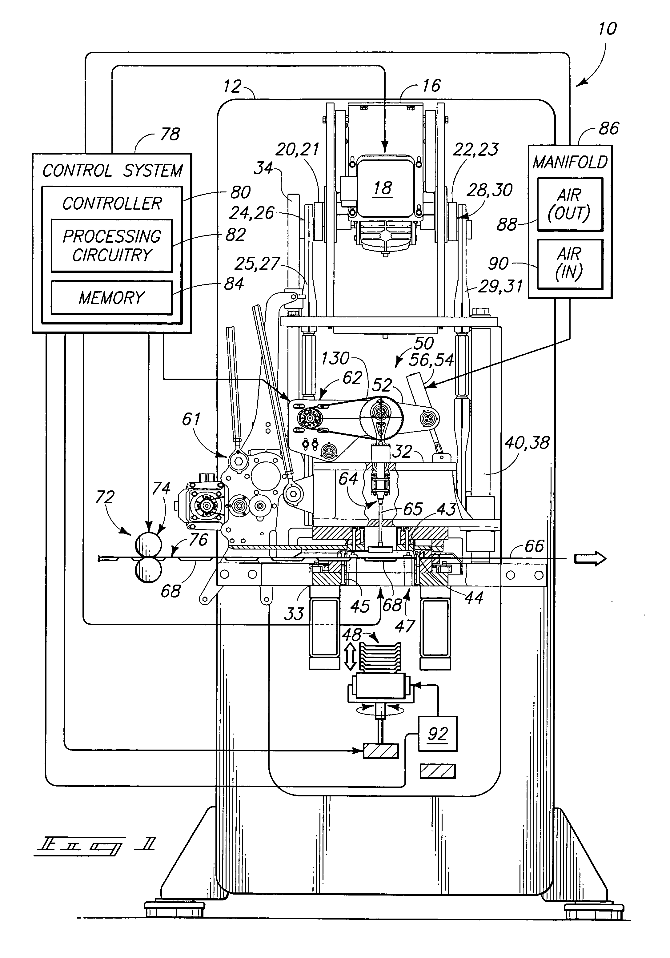
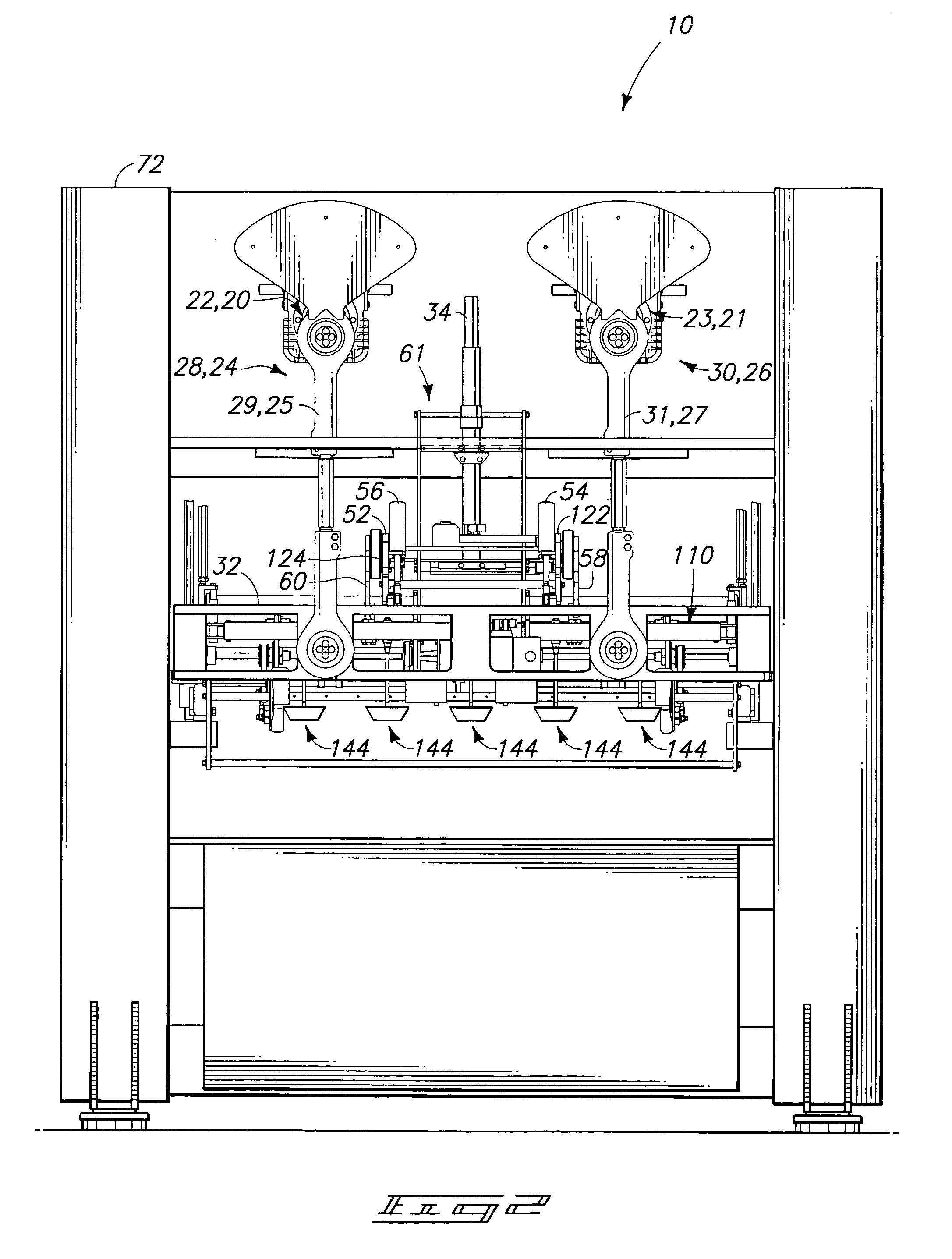
[0033]Reference will now be made to a preferred embodiment of Applicant's invention. An exemplary implementation is described below and depicted with reference to the drawings comprising an article ejector and method for ejecting articles and material from a die assembly in an article accumulator of a thermoforming trim press.

[0034]While the invention is described by way of the preferred embodiment, it is understood that the description is not intended to limit the invention to this embodiment, but is intended to cover alternatives, equivalents, and modifications which may be broader than this embodiment, such as are included within the scope of the appended claims.

[0035]Furthermore, in an effort to prevent obscuring the invention at hand, only details germane to implementing the present ...


PUM

PropertyMeasurementUnit
distanceaaaaaaaaaa
stroke distanceaaaaaaaaaa
depthaaaaaaaaaa

Abstract

An article ejector is provided having kinematic linkages that drive ejector paddle assemblies in an article ejector mode, as well as a die cleaning mode where the kinematic linkages are driven via rotary motion in a continuous clockwise direction, in both modes, without having to impart changes in direction for the rotary drive mechanisms, and while maintaining maximum mechanical advantage of the kinematic linkages. A method is also provided.

Description

RELATED PATENT DATA[0001]This application claims priority from U.S. Provisional Patent Application Ser. No. 60 / 480,145, which was filed on Jun. 20, 2003, and which is incorporated by reference herein.TECHNICAL FIELD[0002]This invention pertains to apparatus for separating and ejecting thin-walled articles from a sheet of thermoformable plastic material in which the articles have been formed using a thermoforming press. More particularly, the present invention relates to a trim press article-ejecting apparatus, such as an article, or product, ejector.BACKGROUND OF THE INVENTION[0003]Numerous techniques are known for separating thin-walled thermoformed articles from sheets of thermoformable plastic material. The trimming of thermoformed articles from a continuous web or sheet of thermoformable plastic material has long been known in the art. It has been known to form and sever articles from webs of both solid and foamed-plastic material.[0004]Using a thermoforming process, articles ar...

Claims


Application Information

Patent Timeline
Patent Type & Authority Patents(United States)
IPC IPC(8): B29C41/42B29C45/40B29C43/50B29C51/44
CPCB29C43/50B29C51/44B29L2031/712
Inventor IRWIN, JERE F.BERREMAN, JEFFFISK, MARIAN J.
Owner IRWIN JERE F
Why Eureka
Try Eureka