Circuitry for eliminating false lock in delay-locked loops

a delay-locked loop and circuit technology, applied in the field of delay-locked loops, can solve the problems of dlls also suffering from problems, delay in the time it takes to receive the clock signal, and dlls may acquire false locks, and provide more delay than intended

Active Publication Date: 2007-06-19
MARVELL ASIA PTE LTD
View PDF3 Cites 49 Cited by
  • Summary
  • Abstract
  • Description
  • Claims
  • Application Information

AI Technical Summary

Benefits of technology

[0007]It is therefore an object of the prese

Problems solved by technology

For example, if the clock distribution source is located at a distance from the load, the clock signal will not be received by the load instantaneously, i.e., there will be a delay in the time it takes to receive the clock signal.
However, DLLs may also suffer from problems.
One possible problem is that a DLL may acquire fals

Method used


Image

  • Circuitry for eliminating false lock in delay-locked loops
  • Circuitry for eliminating false lock in delay-locked loops
  • Circuitry for eliminating false lock in delay-locked loops

Examples


Embodiment Construction

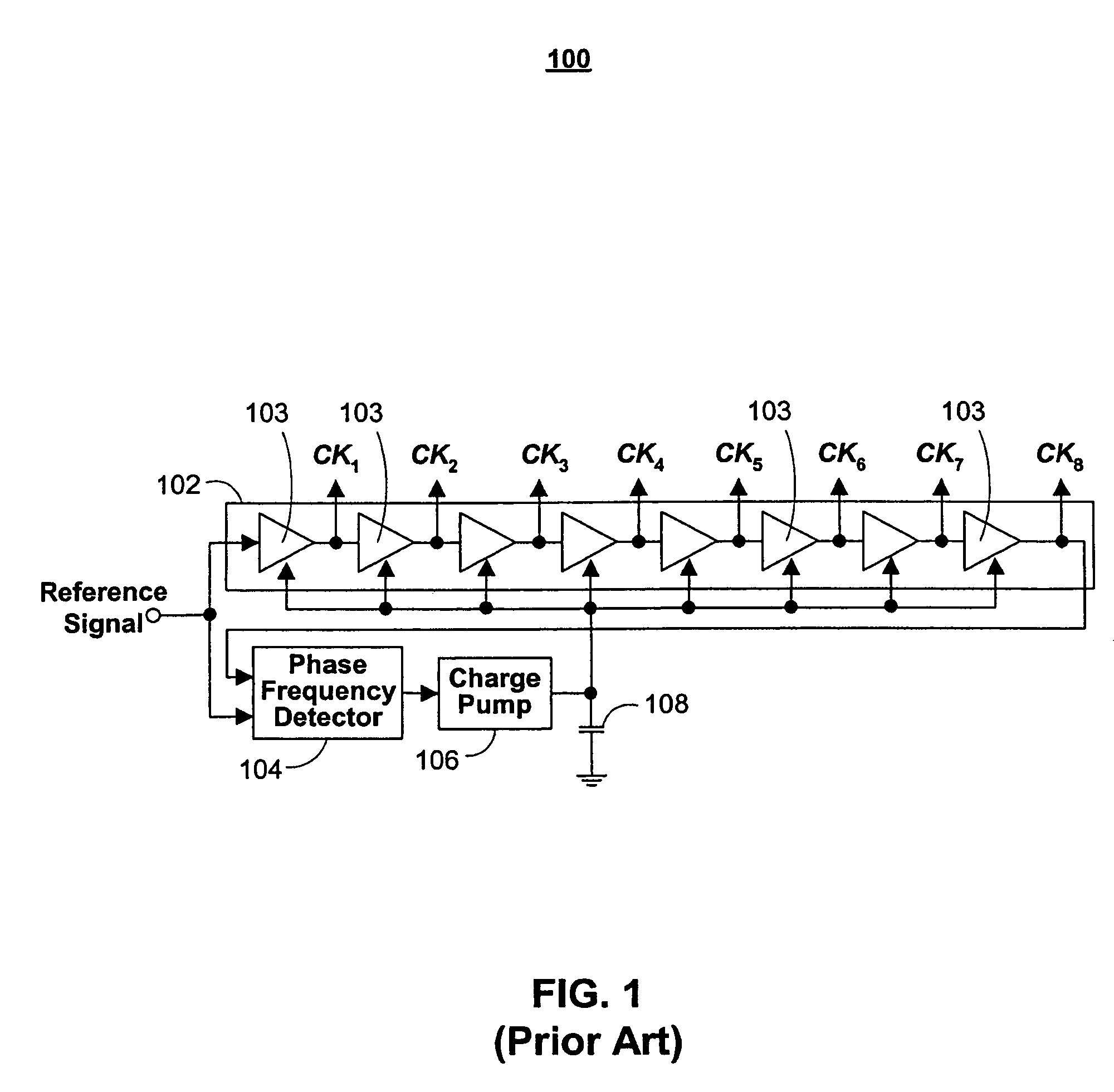
[0023]FIG. 1 is an illustrative block diagram of a prior art DLL 100. DLL 100 may include a delay line 102, a phase frequency detector 104, a charge pump 106, and a capacitor 108.

[0024]Delay line 102 may include a plurality of delay elements 103 connected in series. The number of delay elements may determine the incremental delay that may be provided by DLL 100. For example, in correct lock the total delay on delay line 102 is one period, thus a three-element delay line may provide delay to a signal in increments of thirds of a period, whereas a ten-element delay line may provide delay to a signal in increments of tenths of a period. Each delay element 103 may be controlled by a common control voltage (output by charge pump 106), such that all the delay elements contribute the same amount of delay.

[0025]The control voltage may be monotonically increasing with the delay or monotonically decreasing with the delay. For example, if the control voltage is monotonically increasing with th...


PUM


Abstract

A delay-locked loop (DLL) acquires correct lock when the delay line on the DLL delays a reference signal by one clock period. False lock occurs when the delay line delays the reference signal by more than one clock period. False lock may be detected by a false lock detector. The false lock detector may include (1) flip-flops to take samples of the delay line outputs and (2) combinational logic for detecting patterns in the samples that may indicate false lock. Once false lock has been detected, a hold circuit may ensure that false lock persists for at least the amount of time required by the DLL to acquire lock (i.e., to prevent reset of the DLL before it has acquired lock). After this determination is made, a reset generator may produce a reset signal for resetting the DLL.

Description

CROSS REFERENCE TO RELATED APPLICATION[0001]This application is a non-provisional patent application claiming the benefit of U.S. provisional patent application No. 60 / 635,346, filed Dec. 10, 2004, which is hereby incorporated by reference herein in its entirety.BACKGROUND OF THE INVENTION[0002]This invention relates to delay-locked loops (DLLs) and, more particularly, to circuitry for eliminating false lock in DLLs.[0003]A DLL may be used to provide delayed copies of a reference signal (e.g., a clock signal), which may be routed to digital circuit elements (e.g., flip-flops, registers, etc.). The DLL may include delay elements, which may be connected in series to create a delay line. When the total delay on the delay line is equal to one period of the reference signal, the DLL is considered to have acquired lock. The DLL detects for this by determining when the reference signal and the delay line output are edge-aligned. Once the DLL has acquired lock, the outputs of the individual...

Claims


Application Information

Patent Timeline
IPC IPC(8): H03L7/00
CPCH03L7/0812H03L7/10H03L7/0891H03L7/0816
Inventor SAVOJ, JAFAR
Owner MARVELL ASIA PTE LTD
Why Eureka
Try Eureka