Multi-path dynamic routing algorithm

Inactive Publication Date: 2007-06-19
INTEL CORP
View PDF12 Cites 76 Cited by
  • Summary
  • Abstract
  • Description
  • Claims
  • Application Information

AI Technical Summary

Problems solved by technology
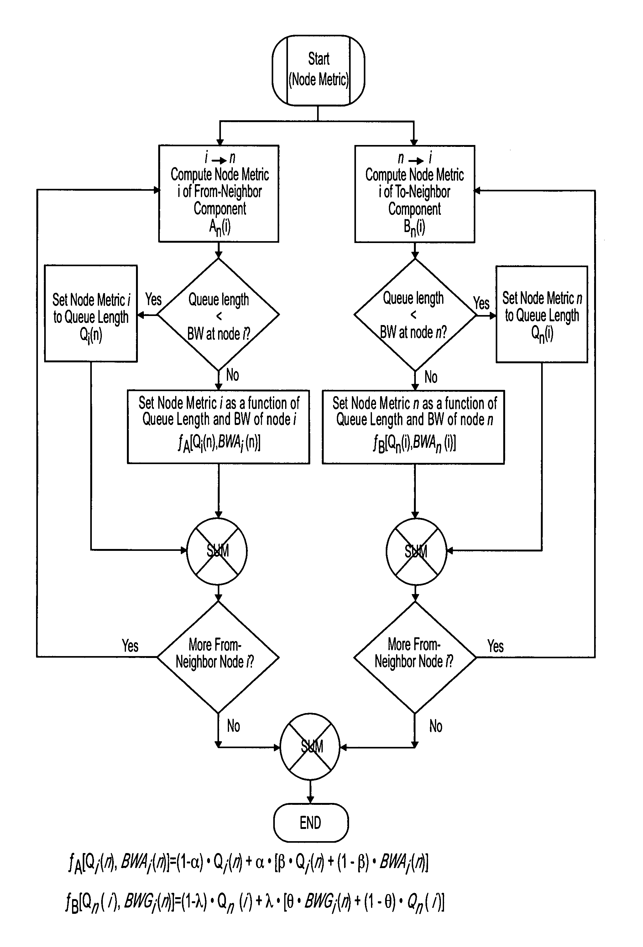
Not all these factors are useful in real networks.
In particular, improper use of link utilization in link metrics may create path oscillation.
First, a hop count metric does not reflect the merit of the path.
Secondly, metric assignments based on link bandwidth also have disadvantages if applied to network 200.

Method used


Image

  • Multi-path dynamic routing algorithm
  • Multi-path dynamic routing algorithm
  • Multi-path dynamic routing algorithm

Examples


Embodiment Construction

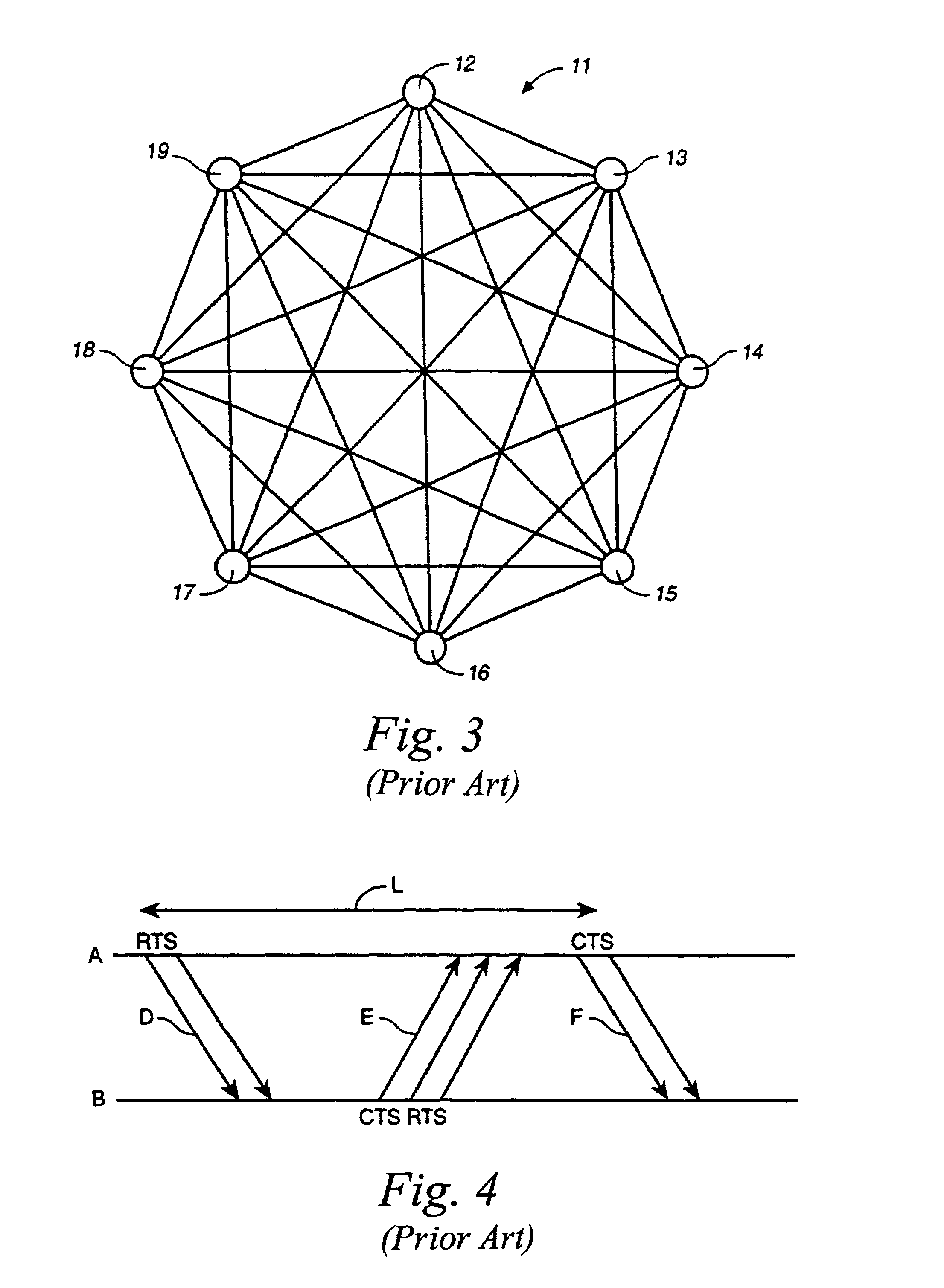
[0024]The following description of a network environment in which the algorithm of the present invention may be employed is taken from U.S. patent application Ser. No. 09 / 589,631, filed Jun. 7, 2000, owned by the assignee of the present invention. Other networks are possible, so long as the node metrics are based upon future incoming and outgoing traffic. With reference to FIG. 3, a wireless mesh topology network 11 of the prior art is shown having mutually interconnected nodes. In the present invention, all nodes need not be interconnected, so long as a node has line of sight communication with at least one neighbor, with the neighbor being in line of sight communication with the rest of the network on the same basis. Communication between nodes is by packets using a known protocol. The basic features of the protocol are as follows.

Sample Protocol

[0025]Time is broken up into frames of known length. In each frame, every node has scheduled slots with which to exchange control informa...


PUM


Abstract

Disclosed is a routing algorithm that uses a new concept of node metric system for optimizing the throughput of a network, in particular, a shared medium network. The measure of congestion of a path in the network is represented by a path metric which is computed by summing the node metrics of the intermediate nodes on the path. Factors used in computing node metrics include the following: 1. future traffic load from neighboring nodes to the node; and 2. future traffic load from the node to the neighboring nodes.

Description

CROSS-REFERENCE TO RELATED APPLICATION[0001]This application is a continuation-in-part of prior application Ser. No. 09 / 589,631, filed Jun. 7, 2000, now abandoned.TECHNICAL FIELD[0002]The invention relates to a method for improving routing in data networks. In particular, the invention discloses a method for routing data in shared media networks based upon dynamic, algorithmic path metric evaluation.BACKGROUND ART[0003]Metrics are numbers associated with a telecommunications network that allow comparison of various paths connecting the same pair of source-destination routers. In U.S. Pat. No. 4,905,233 to Cain et al., there is a disclosed use of path metrics for establishing a transmission route between a source node and a destination node in a multinode communications network. The method involves monitoring transmission characteristics of each of the transmission paths among the respective nodes of the network so as to derive a plurality of path metrics representative of the abilit...

Claims


Application Information

Patent Timeline
IPC IPC(8): H04L12/28H04L12/56
CPCH04L45/12H04L45/123
Inventor WORFOLK, PATRICK A.PLOTKIN, SERGERAVID-RABINOVITZ, SHMUELAARONSON, ITAI
Owner INTEL CORP
Why Eureka
Try Eureka