Optical fiber and optical device using the same
a technology of optical fiber and optical device, applied in the direction of cladded optical fiber, multiplex communication, instruments, etc., can solve the problems of difficult fabrication itself, difficult to uniformly place and size holes in the holey fiber, and difficult in the practical fabrication field to achieve uniform hole locations and sizes, and achieve low cost and low cost. , the effect of efficient generating sc ligh
- Summary
- Abstract
- Description
- Claims
- Application Information
AI Technical Summary
Benefits of technology
Problems solved by technology
Method used
Image

Examples
embodiment 1
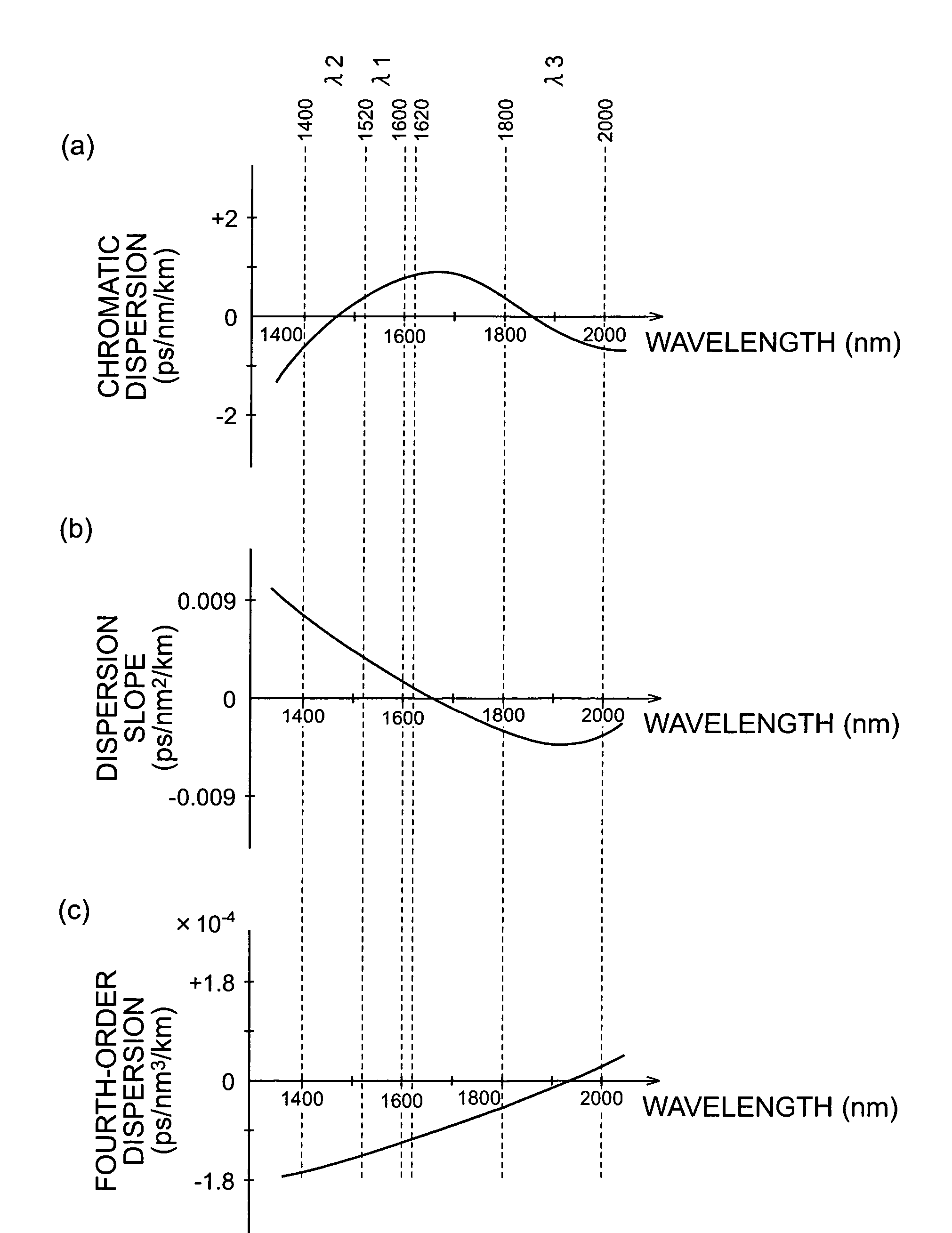
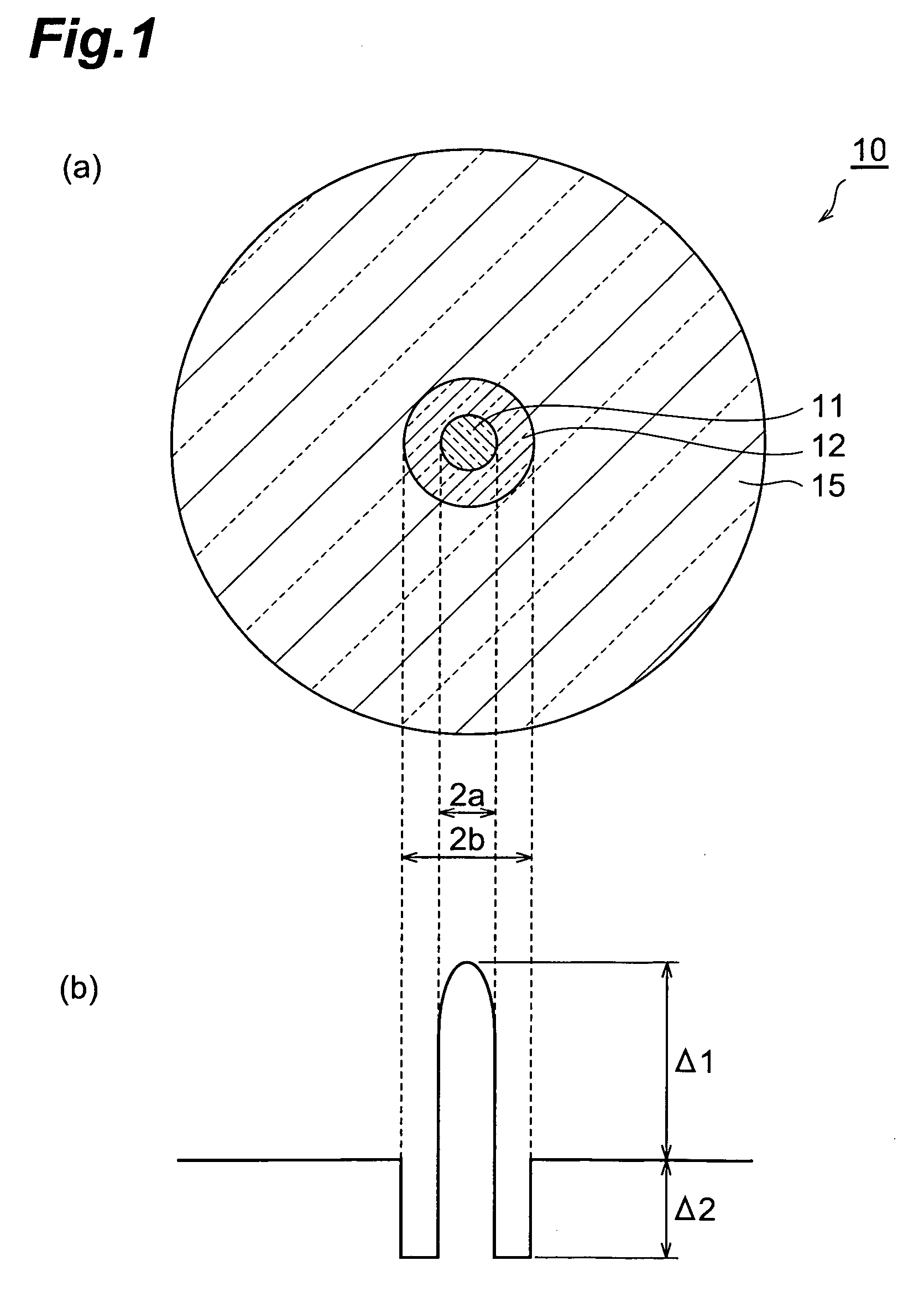
[0097]The optical fiber according to Embodimente 1 has the first structure shown in FIG. 1. FIG. 11 is a refractive index profile of the optical fiber according to Embodiment 1 (showing the refractive indices of the respective portions along the radial direction). FIG. 12 is a graph showing the wavelength dependence of chromatic dispersion in the optical fiber according to Embodiment 1. FIG. 13 is a graph showing the wavelength dependence of dispersion slope in the optical fiber according to Embodiment 1. FIG. 14 is a graph showing the wavelength dependence of fourth-order dispersion in the optical fiber according to Embodiment 1.
[0098]In the optical fiber according to Embodiment 1, as shown in FIG. 11, the relative refractive index difference Δ1 of the center core region with respect to the outside cladding region is 1.42%, and the relative refractive index difference Δ2 of the first depressed region with respect to the outside cladding region is −0.83%. The ratio Ra (=2a / 2b) is 0....
embodiment 2
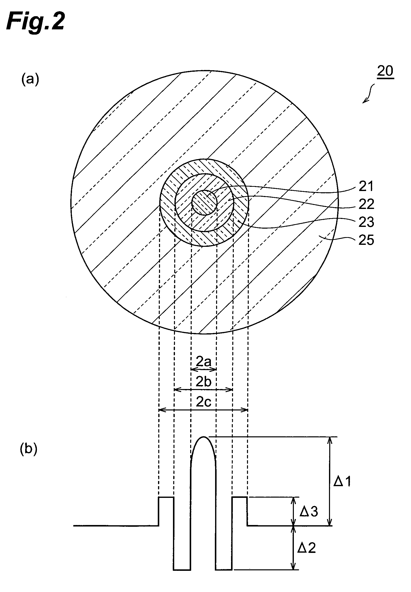
[0101]The optical fiber according to Embodiment 2 has the third structure shown in FIG. 3. FIG. 15 is a refractive index profile of the optical fiber according to Embodiment 2 (showing the refractive indices of the respective portions along the radial direction). FIG. 16 is a graph showing the wavelength dependence of chromatic dispersion in the optical fiber according to Embodiment 2. FIG. 17 is a graph showing the wavelength dependence of dispersion slope in the optical fiber according to Embodiment 2. FIG. 18 is a graph showing the wavelength dependence of fourth-order dispersion in the optical fiber according to Embodiment 2.
[0102]In this optical fiber according to Embodiment 2, as shown in FIG. 15, the relative refractive index difference Δ1 of the center core region with respect to the outside cladding region is 1.42%, the relative refractive index difference Δ2 of the first depressed region with respect to the outside cladding region is −0.83%, the relative refractive index d...
embodiment 3
[0105]The optical fiber according to Embodiment 3 has the third structure shown in FIG. 3. FIG. 19 is a refractive index profile of the optical fiber according to Embodiment 3 (showing the refractive indices of the respective portions along the radial direction). FIG. 20 is a graph showing the wavelength dependence of chromatic dispersion in the optical fiber according to Embodiment 3. FIG. 21 is a graph showing the wavelength dependence of dispersion slope in the optical fiber according to Embodiment 3. FIG. 22 is a graph showing the wavelength dependence of fourth-order dispersion in the optical fiber according to Embodiment 3.
[0106]In this optical fiber according to Embodiment 3, as shown in FIG. 19, the relative refractive index difference Δ1 of the center core region with respect to the outside cladding region is 1.72%, the relative refractive index difference Δ2 of the first depressed region with respect to the outside cladding region is −0.83%, the relative refractive index d...
PUM
 Abstract
Description
Claims
Application Information
 - R&D Engineer
- R&D Manager
- IP Professional
- Industry Leading Data Capabilities
- Powerful AI technology
- Patent DNA Extraction
Browse by: Latest US Patents, China's latest patents, Technical Efficacy Thesaurus, Application Domain, Technology Topic.
© 2024 PatSnap. All rights reserved.Legal|Privacy policy|Modern Slavery Act Transparency Statement|Sitemap