
Method for creating a workflow

Inactive Publication Date: 2007-06-19
OCE TECH
View PDF9 Cites 45 Cited by
  • Summary
  • Abstract
  • Description
  • Claims
  • Application Information

AI Technical Summary

Benefits of technology

[0007]Accordingly, it is an object of the present invention to provide a method for creating a workflow that makes more efficient use of available resources.
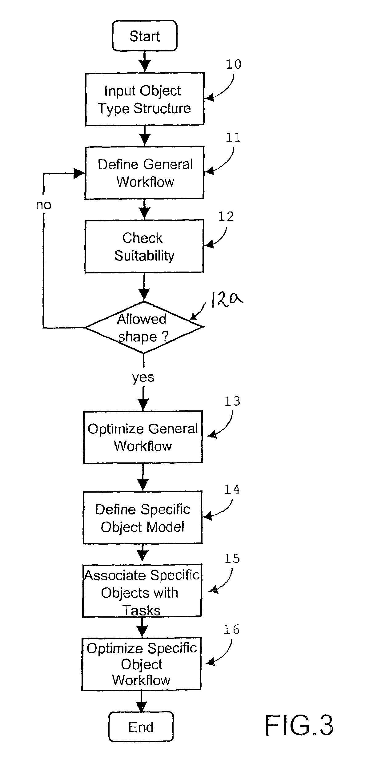
[0009]To this end, a method for creating a workflow according to an embodiment of the present invention comprises rearranging the tasks on the basis of the associated element type for creating parallel task-element combinations in the specific workflow. Thus, the allocation of tasks to participants is performed in an effective and efficient manner. The resultant workflow allows greater concurrency of performance of tasks when it is later carried out.
[0012]The method for creating a workflow according to the present invention is primarily intended for use in programmable processing devices, for instance, a computer or automated processing equipment. It is therefore advantageous to use a suitable representation of object and workflow. To this end, the present method comprises modelling the workflow as a Petri-Net, which includes places representing a task, transitions, and directed connections between the places and transitions. Such a model of the workflow makes the present method well suited to implementation in a computer program, for instance, using object oriented programming techniques.

Problems solved by technology

The automatic association of tasks with objects saves time and money during the scheduling process.
However, the conventional method for creating a workflow takes insufficient account of the resources available for accomplishing various tasks.
This can lead to a workflow in which people or machines wait idly for another task.
Such a workflow results from a lack of insight into the way in which objects are mutually dependent.

Method used


Image

  • Method for creating a workflow
  • Method for creating a workflow
  • Method for creating a workflow

Examples


Embodiment Construction

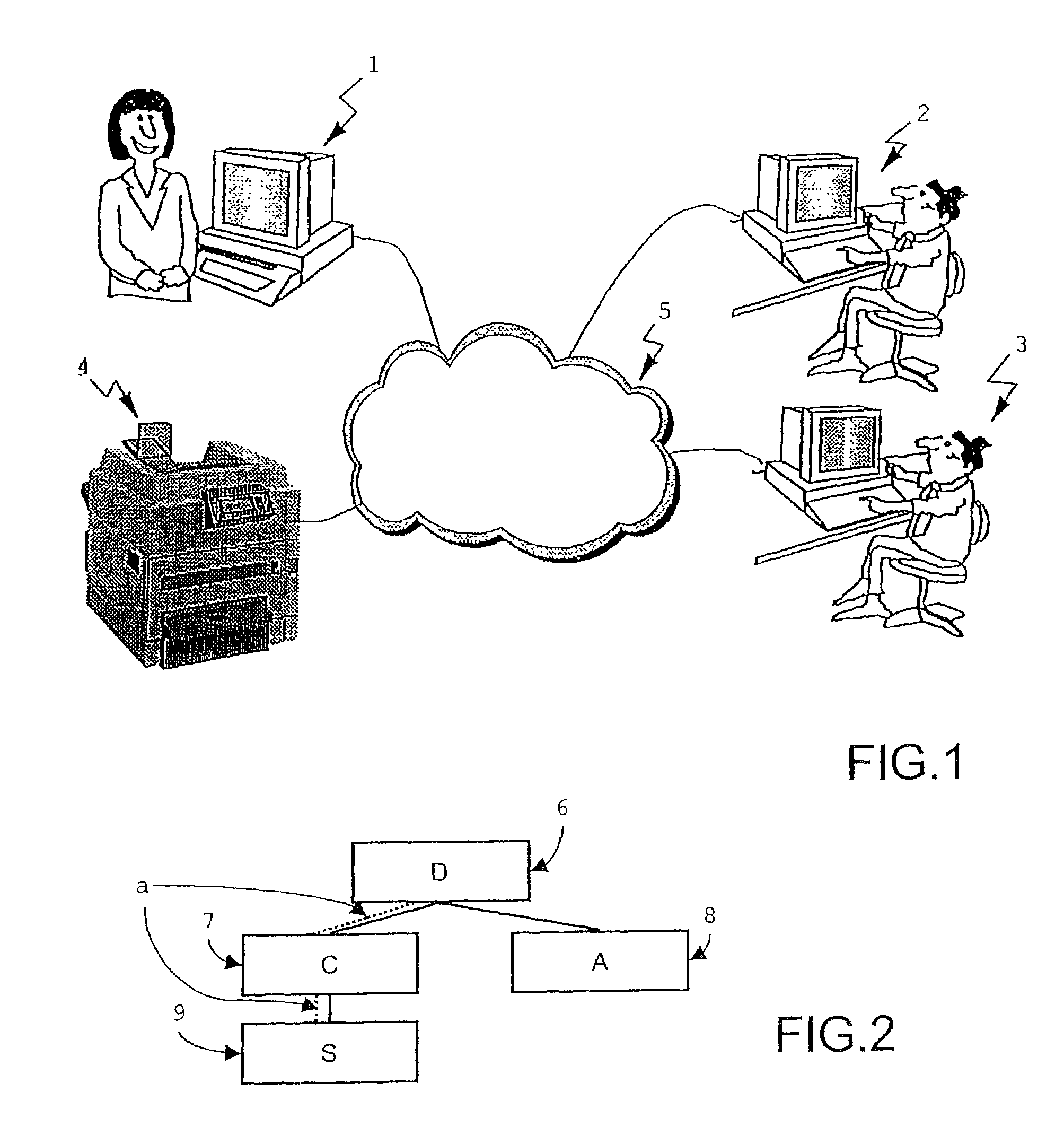
[0025]A workflow can be described as a schedule of a process in whole or part, during which objects, documents, information or tasks are passed from one participant to another for action, according to a set of procedural rules. Almost any process or object can be incorporated in such a workflow.

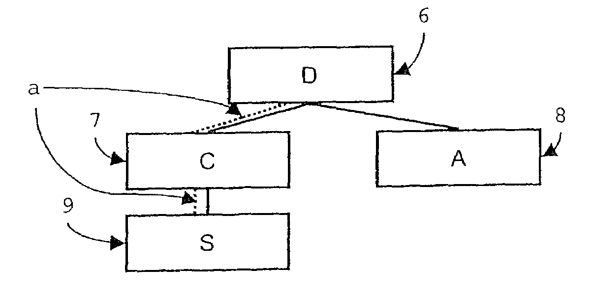
[0026]One example is the creation (the process) of a document (the object) by members of a group of coworkers 1–4, as illustrated in FIG. 1. In the present invention, individuals and / or individuals' devices belonging to a group are referred to as coworkers. The coworkers may possess different types of equipment and / or skills. For example, the first member of the group may be the group leader 1. She could have at her disposal a computer with software for scheduling, making presentations, etc. The second member could be a technical writer 2 located in the R&D centre. He may have at his disposal a word processor and CAD-system. His other coworker could be a translator 3 located in his native cou...


PUM


Abstract

A method for creating a workflow including at least one structured process with interdependent tasks, and a composite object involved in the process is provided. The method includes defining a model of the object, describing the composite object as an aggregate of constituent elements, wherein each element is an instance of an element type; creating a general workflow by modelling the process as a structured graph comprising tasks with an associated element type, connected according to their dependencies; and associating tasks with elements according to their type to create a specific workflow. The method comprises rearranging the tasks on the basis of the associated element type to increase the number of parallel task-element combinations in the specific workflow. A programmable processing device comprises a mechanism for automatically generating a workflow and a mechanism for operation by one or more users. The device uses the above-described method. A computer program product can be run on a computer to execute the method and automatically create a workflow.

Description

BACKGROUND OF THE INVENTION[0001]The present application claims, under 35 USC §119, the foreign priority benefit based on European Patent Application No. 01202762.9 filed Jul. 19, 2001, the entire contents of which are herein fully incorporated by reference.[0002]1. Field of the Invention[0003]The invention relates to a method for creating a workflow comprising at least one structured process with interdependent tasks, and a composite object, e.g., a report or manual, involved in the process. The invention also relates to a programmable processing device comprising means for automatically generating a workflow and means for operation by one or more users and to a computer program product.[0004]2. Discussion of the Related Art[0005]A conventional method of creating a workflow is described in “A Process Model and System for Supporting Collaborative Work”, by Sarin et al., SIGOIS Bulletin, 12 (2 / 3), 1991, p. 213–224. This method disclosed therein comprises decomposing a collaborative p...

Claims


Application Information

Patent Timeline
IPC IPC(8): G06F9/46G06Q10/00
CPCG06Q10/06G06Q10/10Y10S707/99934
Inventor DORTMANS, HENRICUS M. J. M.
Owner OCE TECH
Learn More