
Travel lock for vehicle slide-out

a technology for vehicles and locks, applied in vehicle sanitation, transportation and packaging, transportation items, etc., can solve problems such as inconvenient use for people, and achieve the effect of convenient adaptation to power-assisted deployment and low strain

Active Publication Date: 2007-06-26
LIPPERT COMPONENTS MFG INC
View PDF8 Cites 12 Cited by
  • Summary
  • Abstract
  • Description
  • Claims
  • Application Information

AI Technical Summary

Benefits of technology

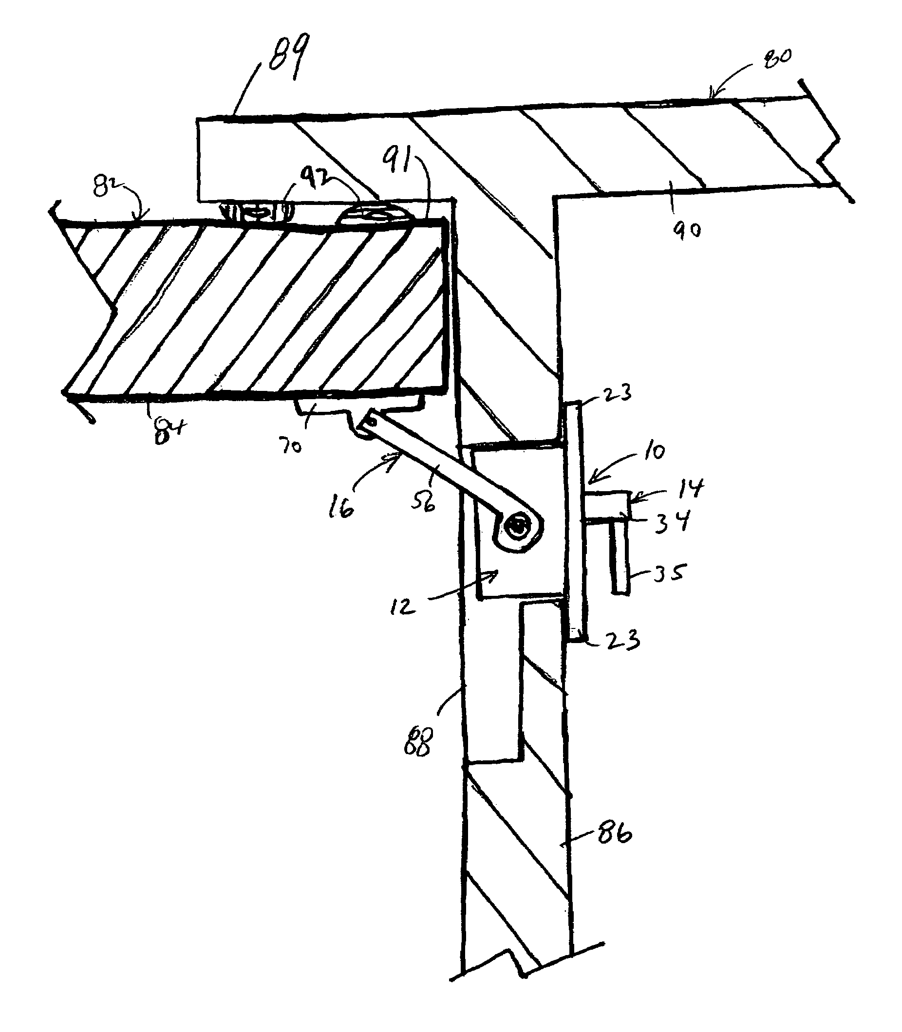
[0014]One or more or the travel stops of the present invention can be used to clamp against an interior surface of a fixed vehicle wall so that the slide-out section is retained securely in a retracted position to keep the slide-out section stationary with respect to the rest of the vehicle during transit. The travel stop is compact, light-weight and inexpensive. It can be mounted in a small opening in a wall of the slide-out section for access from the interior of the slide-out section. Its small size makes it inconspicuous to persons inside the slide-out section, especially with the handle removed. Its small size also makes it unnecessary to leave a large unoccupied space around the perimeter of the slide-out section. The travel stop “folds” out of the way so as not to interfere with extension of the slide-out section when desired. The travel stop can be deployed manually with a low strain cranking motion. Moreover, it is readily adapted for power-assisted deployment using an electric motor.

Problems solved by technology

Its small size makes it inconspicuous to persons inside the slide-out section, especially with the handle removed.
Its small size also makes it unnecessary to leave a large unoccupied space around the perimeter of the slide-out section.

Method used


Image

  • Travel lock for vehicle slide-out
  • Travel lock for vehicle slide-out
  • Travel lock for vehicle slide-out

Examples


Embodiment Construction

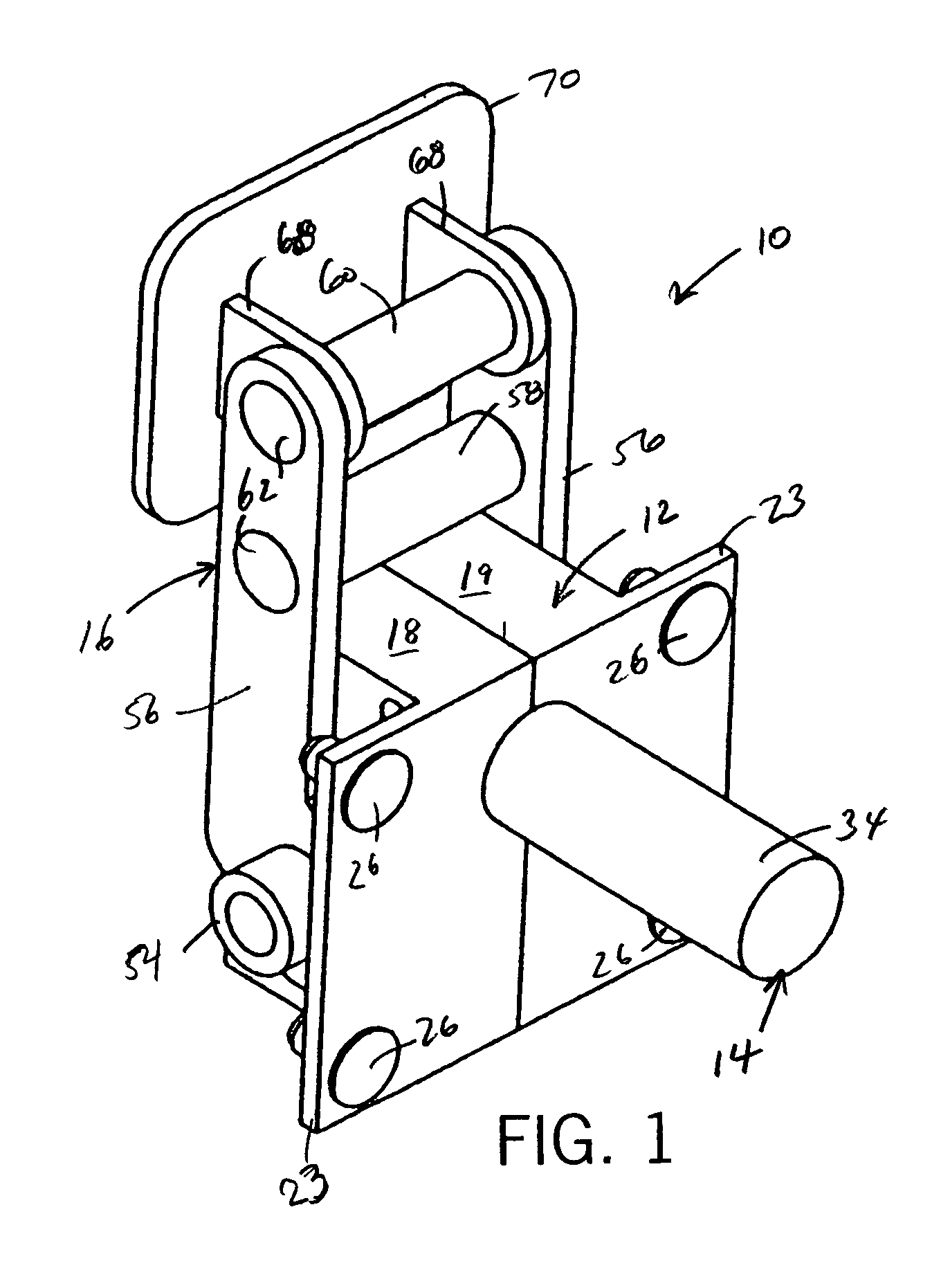
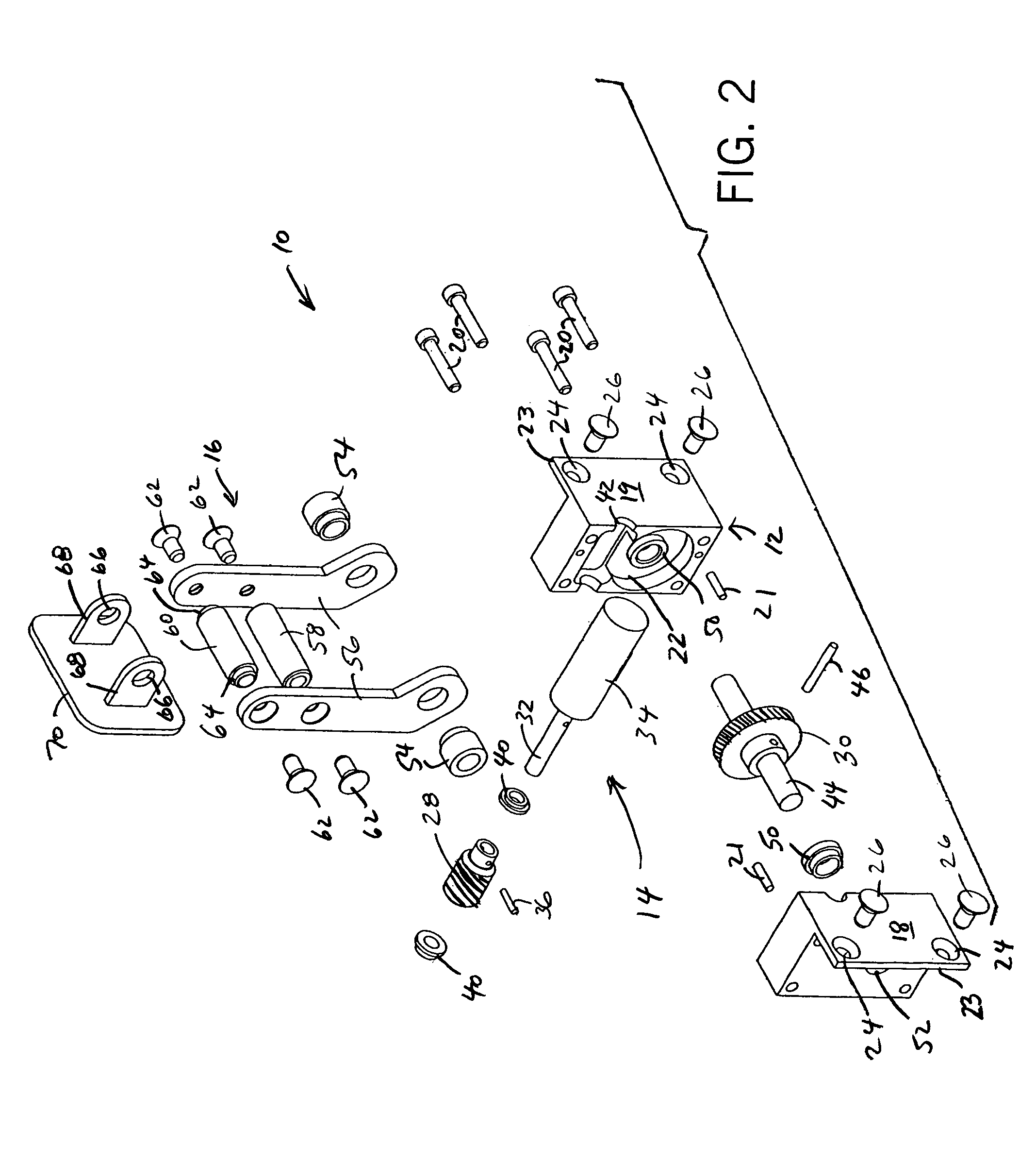
[0021]Referring to FIGS. 1–3, the travel stop 10 includes a gear box 12 housing an actuator 14 which moves a pivot assembly 16 between collapsed (see FIG. 4) and engaged (see FIG. 5) positions. Specifically, the gear box 12 is of two-piece machined aluminum construction having symmetric left 18 and right 19 parts joined by four bolts 20 and two dowels 21. The mating faces of these parts define pockets or recesses 22 accommodating the actuator 14 and their opposite ends define flanges 23 with bolt holes 24 for cap screws 26 to mount the gear box 12 in a recess in a side wall of a slide-out room. In this case, the stop 10 is inserted into the side wall recess from the interior surface of the side wall (See FIG. 4) and the screws that go through the holes 26 penetrate the interior surface of the slide-out room side wall, with minimal intrusion of the stop 10 into the slide-out room.

[0022]Referring to FIG. 2, the actuator 14 is a mating gear arrangement having a drive gear 28 and a driv...


PUM


Abstract

A gear operated pivoting travel lock secures a slide-out section of a vehicle in a retracted position. The travel lock includes a gear box, containing two mating worm gears, that mounts to a wall of the slide-out section. The drive gear is mounted at the end of an operating member and the driven gear is mounted to an axle. Two pivot arms are mounted at the ends of the axle. Turning the operating member, preferably by a handle member, rotates the drive gear to mesh with the driven gear. As the driven gear rotates, the pivot arms swing out from a collapsed position to an engaged position. When the slide-out section is retracted within the vehicle, a pressure pad at the end of the pivot arms clamps against an interior surface of the vehicle wall. When the travel lock is collapsed the slide-out section can be moved between the retracted and extended positions.

Description

CROSS-REFERENCE TO RELATED APPLICATION[0001]This application claims benefit to U.S. Provisional Patent Application No. 60 / 538,378 filed Jan. 22, 2004.STATEMENT OF FEDERALLY SPONSORED RESEARCH OR DEVELOPMENT[0002]Not applicable.BACKGROUND OF THE INVENTION[0003]1. Technical Field[0004]The present invention relates to vehicles having slide-out sections, and in particular to devices for securing the slide-out sections when retracted.[0005]2. Description of the Related Art[0006]Vehicles (including self-powered vehicles and non-powered trailers) having interiors with living space, such as recreational vehicles (RVs), are well-known. In order to increase the interior living space available in such vehicles it is known to have slide-out sections, such as rooms and closets, that can be retracted during transit and extended when the vehicle is stationary and intended to be occupied. To use the slide-out section, the vehicle is first parked and leveled and then the slide-out section is extende...

Claims


Application Information

Patent Timeline
Patent Type & Authority Patents(United States)
IPC IPC(8): B60P3/34
CPCB60P3/34
Inventor PETER, GARY D.
Owner LIPPERT COMPONENTS MFG INC
Learn More