Gas-assisted electrosurgical accessory connector and method with improved gas sealing and biasing for maintaining a gas tight seal

a technology of gas sealing and electrosurgical accessories, which is applied in the field of gas sealing electrosurgical accessory connectors and methods with improved gas sealing, can solve the problems of unsatisfactory electrosurgical effect, unsatisfactory electrosurgical effect, and unintended burn to surgeons, operating room personnel or patients

Active Publication Date: 2007-06-26
CONMED CORP
View PDF9 Cites 241 Cited by
  • Summary
  • Abstract
  • Description
  • Claims
  • Application Information

AI Technical Summary

Benefits of technology

[0011]In general, the present invention pertains to a new and improved gas-assisted electrosurgery accessory connector which does not depend on an axial contact seal for confining gas flow within the accessory connector. Instead, the improved accessory connector of the present invention uses a radial compression seal. The radial compression seal maintains a leak-free seal even if the two mating pieces of the accessory connector become somewhat loosened during the course of a surgical procedure. In addition, the new and improved accessory connector biases the two mating pieces of the accessory connector into a fully connected relationship to resist unintentional loosening of the two mating pieces. These and other improvements are achieved in a manner which permits backward-compatible use of certain pre-existing accessory connectors of the type described in U.S. Pat. No. Re 34,780. The backwards compatibility allows the improvements of the present invention to be incorporated in the mating piece of the accessory connector which is connected to the housing of the gas-assisted electrosurgical unit, so that existing previous accessories can be used. Furthermore, improvements in the mating piece of the accessory connector which is attached to the accessory does not prohibit the use of that accessory with the complementary mating piece of the previous form of the accessory connector. Thus, the improvements in both mating pieces of the present accessory connector may be used with the previous forms of the complementary mating pieces unknown gas-assisted accessory connectors, without the necessity to change the mating piece attached to the housing of the gas-assisted electrosurgical unit and without the necessity to purchased new accessories.

Problems solved by technology

If gas leaks from the accessory connector, the desired amount of gas will not be delivered from the nozzle, and the desired electrosurgical effect may not be achieved.
Similarly, if current leakage or conduction of some of the RF energy occurs at the accessory connector, the desired electrosurgical effect may not be achieved.
RF energy leakage at the accessory connector or any other location along the cord or within the handpiece, can cause an unintended burn to the surgeon, operating room personnel or the patient, or may damaged the electrosurgical generator.
Loosening of the two connected mating pieces of the accessory connector, even to a small degree, is likely to cause the sealing surfaces of the accessory connector to separate slightly, resulting in a leak gas.
Since the surgeon expects variations in the surgical effect due to tissue differences, the surgeon may not recognize that the performance of the gas-assisted electrosurgical unit may have become compromised as a result of a gas leak at the accessory connector, resulting from continual movement of the cord and the handpiece during the procedure or from the cord having been accidentally stepped on, pulled or bumped during the surgical procedure.
The gas flow rate through the relatively small diameter gas-conducting tube is less, causing the effect of a relatively small leak to magnify the extent of deviation of the gas flow from the nozzle, thereby impacting the expected performance.

Method used


Image

  • Gas-assisted electrosurgical accessory connector and method with improved gas sealing and biasing for maintaining a gas tight seal
  • Gas-assisted electrosurgical accessory connector and method with improved gas sealing and biasing for maintaining a gas tight seal
  • Gas-assisted electrosurgical accessory connector and method with improved gas sealing and biasing for maintaining a gas tight seal

Examples


Embodiment Construction

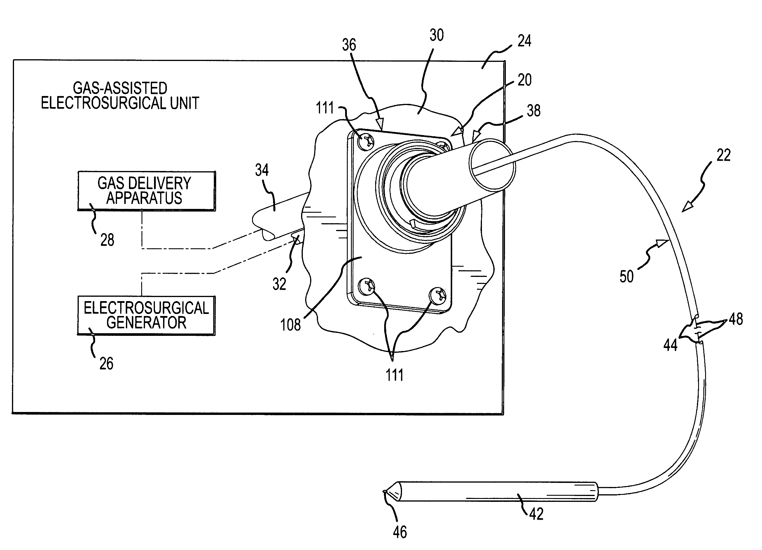
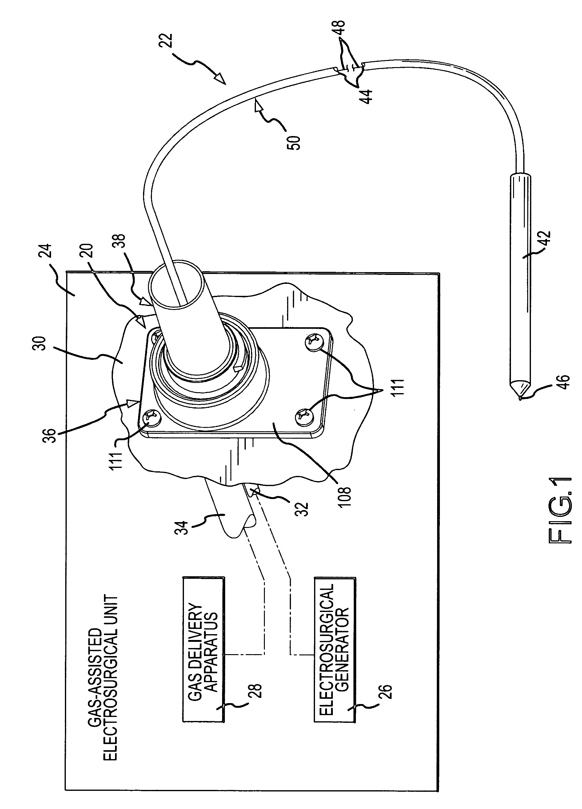
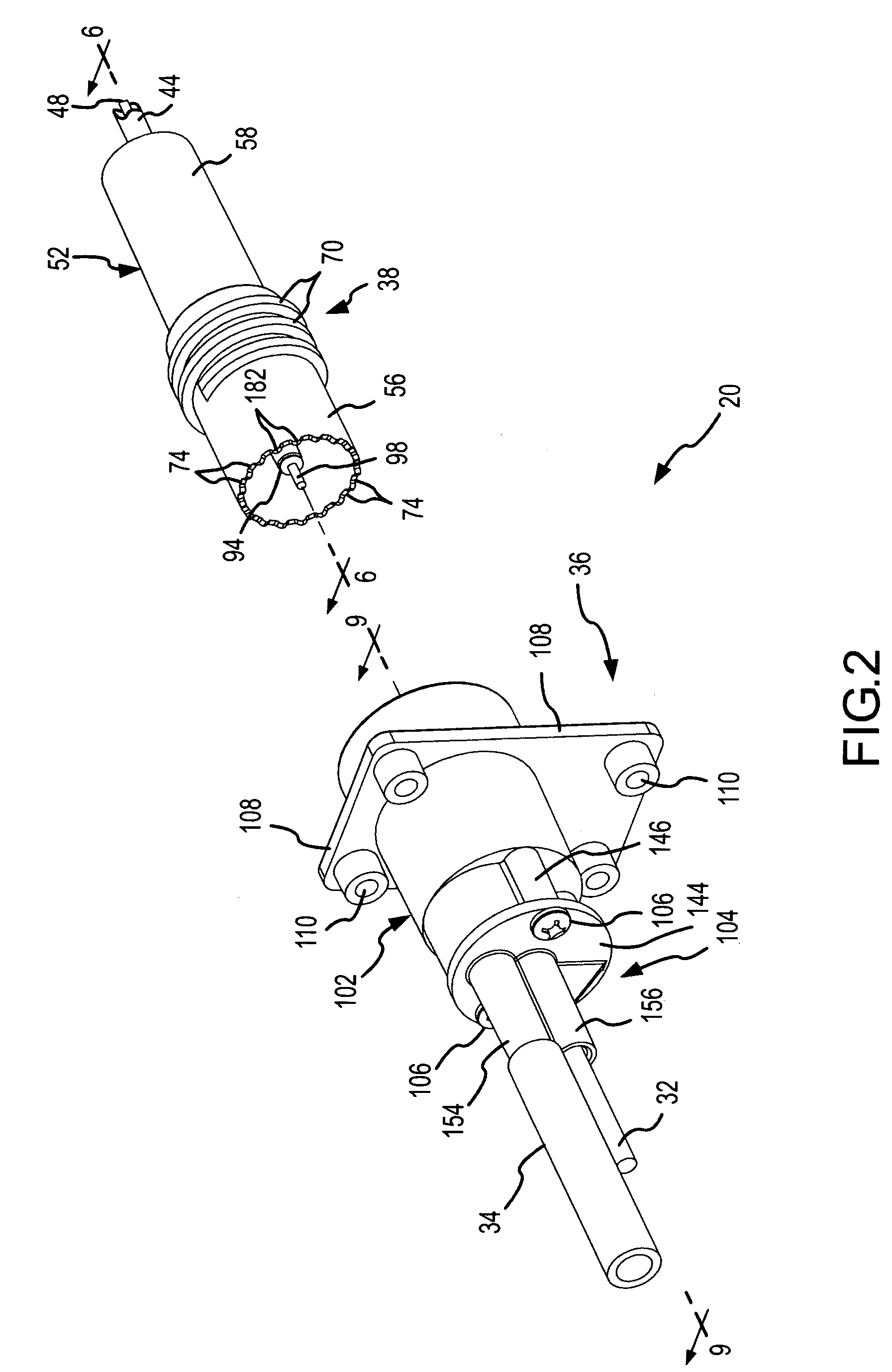
[0035]An accessory connector 20 incorporating the present invention is shown in FIGS. 1 and 2. The accessory connector 20 connects a gas-assisted electrosurgical accessory 22 to a conventional gas-assisted electrosurgical unit 24. The gas-assisted electrosurgical unit 24 includes a conventional electrosurgical generator 26 and a conventional gas delivery apparatus 28, both of which are typically contained wholly or partially within a housing 30 (partially shown) of the gas-assisted electrosurgical unit 24. The electrosurgical generator 26 generates radio frequency (RF) electrical energy of preselected characteristics from conventional alternating current power, and applies the RF electrical energy on a supply conductor 32 within the housing 30. The gas delivery apparatus 28 includes a source of preferably-inert and ionizable gas (not shown), from which a flow of gas of preselected and controlled characteristics is derived and supplied within the housing 30 through a supply conduit 3...


PUM


Abstract

Male and female mating pieces of a gas-assisted electrosurgical accessory connector are connectable together by radially contacting a sealing surface formed on one mating piece with a resilient radially-compressible sealing member carried on the other mating piece. A gas-tight seal exists along a length of the sealing surface as the two mating pieces connect with relative connection movement. The existence of the gas-tight seal over a range of relative connection movement maintains the seal if the mating pieces should become slightly disconnected. The mating pieces are also restrained against separation from one another. A recess is formed in one of the mating pieces and a retention member carried on the other one of the mating pieces is biased into contact with the recess. Separation of the two connected members requires manual force to extract the retention member from the recess. The amount of manual force required is greater than that normally experienced from movement during use, thereby inhibiting unintentional separation.

Description

[0001]This invention relates to gas-assisted electrosurgery, and more particularly to a new and improved accessory connector for connecting a gas-assisted electrosurgical accessory to a gas-assisted electrosurgical unit which includes an electrosurgical generator and a gas delivery apparatus. The accessory connector is less susceptible to gas leaks, is more resistant to unintentional disconnection or separation of internal gas sealing surfaces, and is backwards compatible with certain previous gas-assisted electrosurgical accessory connectors, among other improvements.BACKGROUND OF THE INVENTION[0002]Electrosurgery involves the application of radio-frequency (RF) electrical energy to cut a patient's tissue, to coagulate blood flow from the tissue, or to both cut and coagulate simultaneously. An electrosurgical generator creates the RF electrical energy, and the RF energy is applied to the tissue by an applicator or pencil-like handpiece which is manipulated by a surgeon to cut and c...

Claims


Application Information

Patent Timeline
Patent Type & Authority Patents(United States)
IPC IPC(8): A61B18/18A61M1/00A61B17/00A61B18/00A61B18/14
CPCA61B18/042A61B18/14A61B2017/00477A61B2018/00178A61B2018/00988
Inventor GONNERING, WAYNE J.
Owner CONMED CORP
Why Eureka
Try Eureka