Integral air/oil coalescer for a centrifuge

a centrifuge and air/oil technology, applied in centrifuges, separation processes, filtration separation, etc., can solve the problems of high restriction, difficult to design a high-efficiency coalescer without resorting to for

Inactive Publication Date: 2007-06-26
FLEETGUARD INC
View PDF36 Cites 86 Cited by
  • Summary
  • Abstract
  • Description
  • Claims
  • Application Information

AI Technical Summary

Benefits of technology

[0007]A centrifuge for separating particulate matter from a circulating fluid according to one embodiment of the present invention comprises a centrifuge enclosure including a housing and a base joined together and defining a hollow interior, a rotor positioned in the hollow interior and supported by the base, a coalescing filter assembly secured to the rotor, the coalescing filter assembly being constructed and arranged for removing oil aerosol from a blowby gas, and bearing means positioned between the coalescing filter element and the centrifuge enclosure.

Problems solved by technology

The presence of fine pores in a coalescing filter can result in the pores becoming “clogged” with the liquid being separated, due to the surface tension and the corresponding “bridging” effect.
This relatively high surface tension causes a correspondingly high restriction since it takes a large pressure to overcome the surface tension across a small wetted pore.
Since engine crankcase pressure must be kept very near atmospheric pressure, approximately 5 inches of water, it is difficult to design a high-efficiency coalescer without resorting to a fairly elaborate arrangement of pressure control valves, vacuum assist devices, and similar mechanisms.
However, prior designs such as that disclosed in the '595 patent, where the coalescing filter is mounted to a structure such as a gear, have had their performance limited to some degree due to the rather low speed of the rotating component, such as one half of the engine speed.

Method used


Image

  • Integral air/oil coalescer for a centrifuge
  • Integral air/oil coalescer for a centrifuge
  • Integral air/oil coalescer for a centrifuge

Examples


Embodiment Construction

[0022]For the purposes of promoting an understanding of the principles of the invention, reference will now be made to the embodiments illustrated in the drawings and specific language will be used to describe the same. It will nevertheless be understood that no limitation of the scope of the invention is thereby intended, such alterations and further modifications in the illustrated device, and such further applications of the principles of the invention as illustrated therein being contemplated as would normally occur to one skilled in the art to which the invention relates.

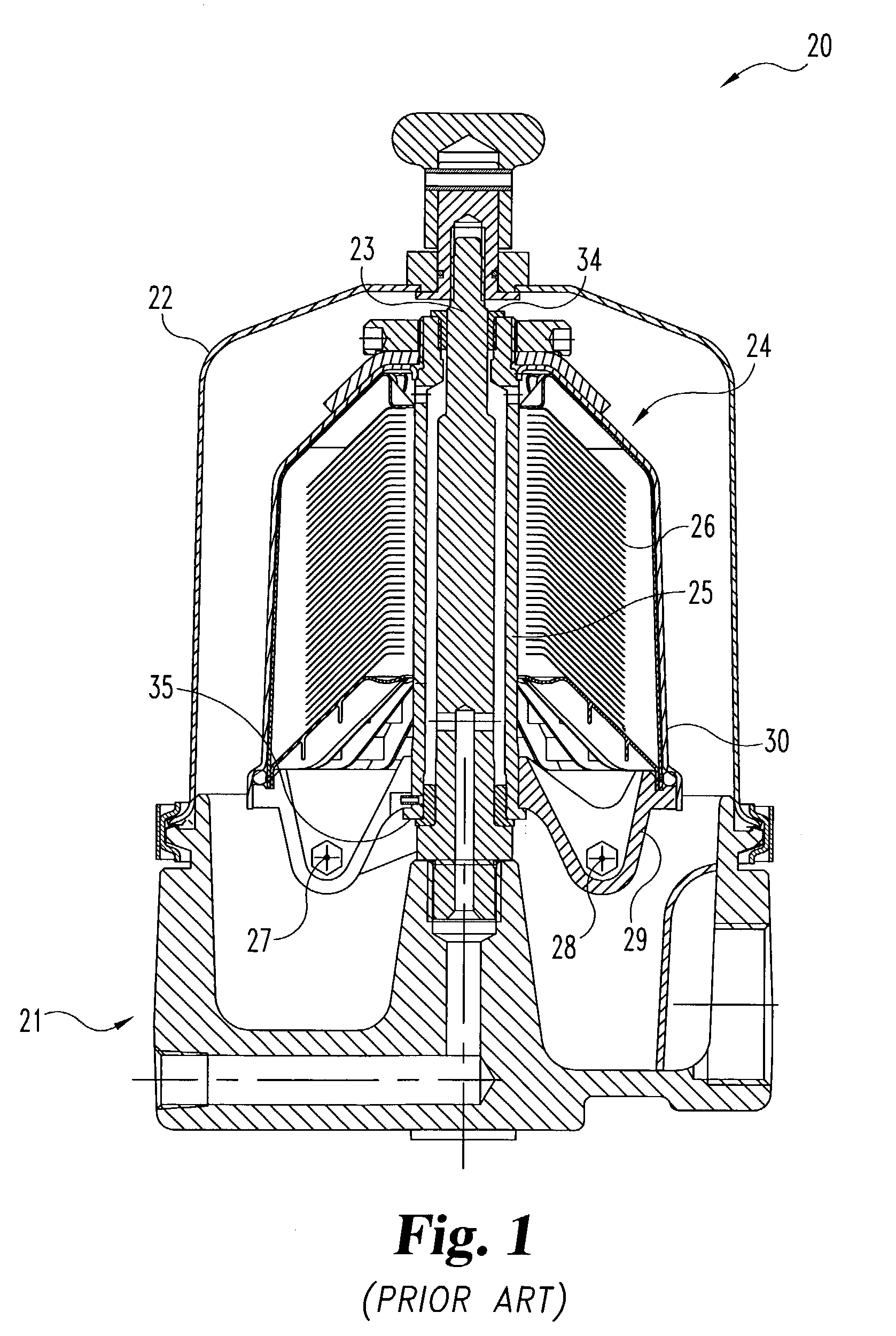
[0023]Referring to FIG. 1, there is illustrated a prior art centrifuge 20 with a take-apart rotor assembly. This illustration is provided in order to help explain the starting centrifuge structure prior to integration of a coalescing filter, according to the present invention. Centrifuge 20 includes, as some of its primary components, base 21, bell housing 22, shaft 23, and rotor assembly 24, including rotor hu...


PUM

PropertyMeasurementUnit
incline angleaaaaaaaaaa
flexibleaaaaaaaaaa
speedaaaaaaaaaa

Abstract

A centrifuge for separating particulate matter from circulating fluid includes a centrifuge enclosure including a housing and a base joined together so as to define a hollow interior. A rotor is positioned in the hollow interior and is supported by the base in a manner to permit rotary motion of the rotor relative to the centrifuge enclosure. A coalescing filter assembly is secured to the rotor and is constructed and arranged for removing oil aerosol from a blowby gas which is introduced into the centrifuge. A roller bearing, press fit into the centrifuge housing, receives a portion of the coalescing filter assembly.

Description

BACKGROUND OF THE INVENTION[0001]The present invention relates in general to diesel engine filtration systems and in particular to a coalescing filter to remove oil aerosol from a blowby gas (exhaust) stream. More specifically, the present invention relates to a coalescing filter which is subjected to rotation in order to expel the coalesced liquid from the filter and thereby keep any flow restriction within the filter comparatively low.[0002]The present invention focuses on the addition of an air / oil coalescing filter as part of a rotating lube bypass centrifuge in order to remove oil aerosol from blowby gas associated with an internal combustion engine crankcase ventilation system. The coalescing filter is subjected to high-speed rotation which assists in expelling the coalesced liquid (oil) from the filter. This in turn helps to maintain a low filter restriction and a low crankcase pressure.[0003]In order to achieve high separation efficiency for oil aerosol in the 0.1–1.0 micron...

Claims


Application Information

Patent Timeline
Patent Type & Authority Patents(United States)
IPC IPC(8): B01D33/00B04B5/00B04B5/10F01M13/04
CPCB04B5/005B04B5/10F01M13/04F01M2013/0422F01M2013/0438Y10S210/05
Inventor HERMAN, PETER K.HOVERSON, GREGORY W.AMIRKHANIAN, HENDRIK N.GUICHAOUA, JEAN-LUCLEROUX, BENOITMALGORN, GERARD
Owner FLEETGUARD INC
Why Eureka
Try Eureka