Electric device, a current limiter and an electric power network

Inactive Publication Date: 2007-06-26
ABB (SCHWEIZ) AG
View PDF3 Cites 43 Cited by
  • Summary
  • Abstract
  • Description
  • Claims
  • Application Information

AI Technical Summary

Benefits of technology

[0042]A fourth object of the invention is to provide a

Problems solved by technology

The losses of the apparatus contribute to the losses of the system.
Admittedly this contribution is rather slight but the losses of the apparatus affect its cost since, in many cases, it must be water-cooled, which is expensive.
An apparatus dimension

Method used


Image

  • Electric device, a current limiter and an electric power network
  • Electric device, a current limiter and an electric power network
  • Electric device, a current limiter and an electric power network

Examples


second embodiment

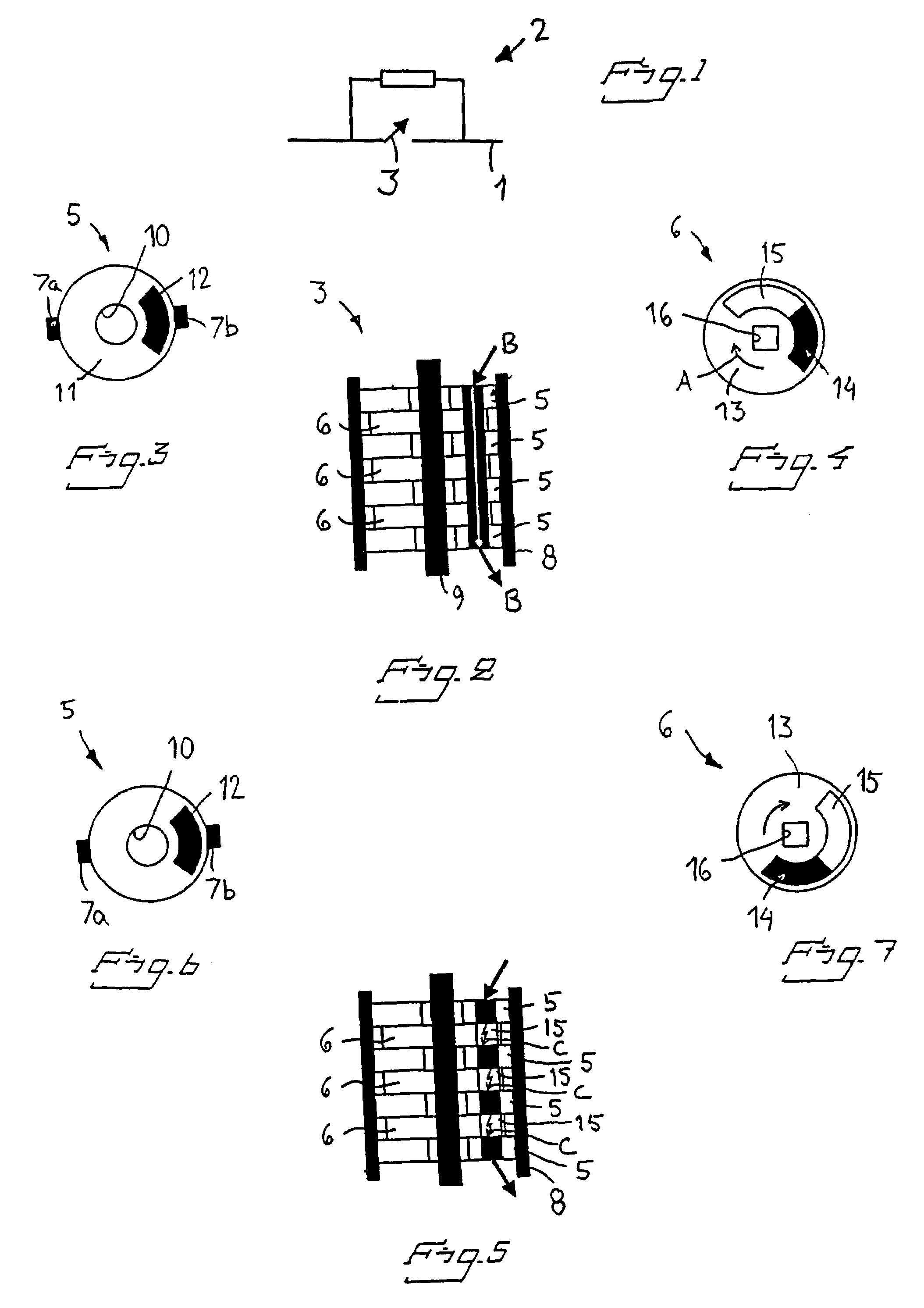
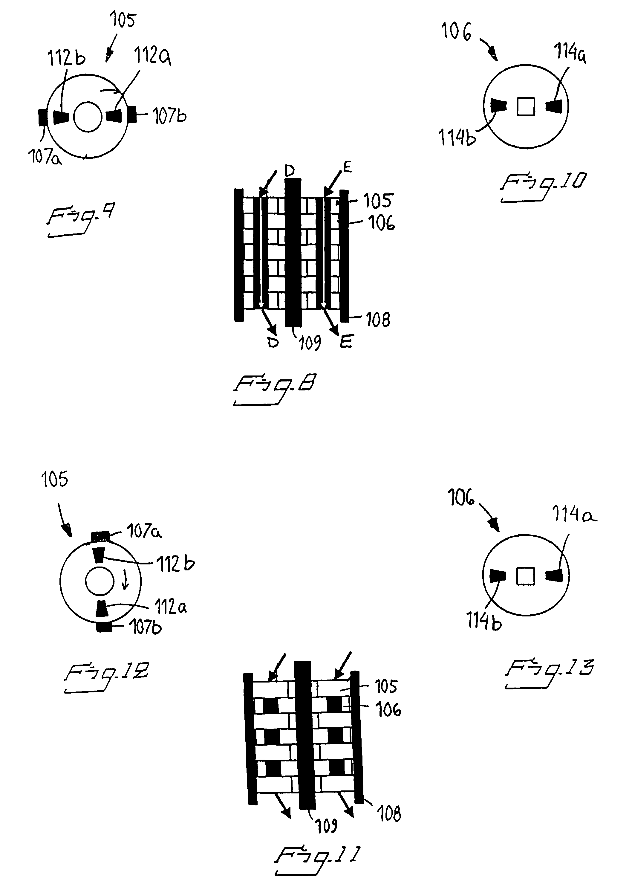
[0051]FIGS. 8–13 show the electric switch in sections / views corresponding to FIGS. 2–7,

first embodiment

[0052]FIG. 14 illustrates a driving power source for the electric switch,

[0053]FIGS. 15 and 16 illustrate a second embodiment of a driving power source in accordance with the invention,

[0054]FIG. 17 illustrates a first embodiment of a current limiter in accordance with the invention,

[0055]FIG. 18 illustrates a second embodiment of a current limiter in accordance with the invention,

[0056]FIG. 19 illustrates an embodiment of an electric power network in accordance with the invention,

[0057]FIG. 20 illustrates an alternative embodiment of an electric power network in accordance with the invention,

[0058]FIGS. 21 and 22 illustrate an alternative embodiment of an electric switch in accordance with the invention in closed and open position, respectively,

[0059]FIGS. 23 and 24 are sections through an actuating mechanism in an electric switch as shown in FIGS. 21 and 22 in closed and open position, respectively.


PUM


Abstract

An electric device including an electric switch having a plurality of contact members arranged in series to form a plurality of breaking points arranged in series. One of the contact members at each breaking point is movable. A drive is arranged to actuate each movable contact member. The drive is arranged to effect simultaneous movement of the movable contact members. A commutation circuit is connected in parallel with the electric switch. Each contact member constitutes a part of a contact element, which contact elements are arranged in series. The contact elements have conducting and insulating parts. Every second contact element is movable in relation the others so that movement effects a breaking or closing position of the electric switch. The invention also includes a current limiter such as an electric device and also an electric power network provided with such a current limiter.

Description

CROSS-REFERENCE TO RELATED APPLICATIONS[0001]This application claims priority to Swedish patent application 0100074-4 filed 11 Jan. 2001 and is the national phase under 35 U.S.C. § 371 of PCT / SE02 / 00034.TECHNICAL FIELD[0002]The present invention relates firstly to an electric device comprising an electric switch having a plurality of contact members arranged in series to form a plurality of breaking points arranged in series, at least one of the contact members at each breaking point being movable, and drive means arranged to actuate each movable contact member.[0003]The invention relates secondly to a current limiter.[0004]The invention relates thirdly to a dynamic voltage restorer.[0005]The invention relates fourthly to an electric power network.[0006]Finally, the invention relates fifthly to use of the current limiter in accordance with the invention.BACKGROUND ART[0007]Certain types of electrical apparatus in electrical systems are such that they are seldom activated but must be...

Claims


Application Information

Patent Timeline
IPC IPC(8): H01H1/14H01H1/00H01H9/00H01H9/40H01H9/42
CPCH01H9/40H01H9/542H01H9/42
Inventor LILJESTRAND, LARSVALDEMARSSON, STEFAN
Owner ABB (SCHWEIZ) AG
Why Eureka
Try Eureka