Laser system for the ionization of a sample by matrix-assisted laser desorption in mass spectrometric analysis

a matrix-assisted laser and mass spectrometric analysis technology, which is applied in the direction of optical resonator shape and construction, particle separator tube details, separation processes, etc., can solve the problems of inability to reproduce pulsed gas discharge, inability to ionize samples, and inability to achieve mass spectrometric analysis quality and robustness significantly improved, the effect of improving the ionization efficiency and mass resolution and even the signal-to-noise ratio

Active Publication Date: 2007-06-26
BRUKER DALTONIK GMBH & CO KG
View PDF9 Cites 39 Cited by
  • Summary
  • Abstract
  • Description
  • Claims
  • Application Information

AI Technical Summary

Benefits of technology

[0021]The basis of the invention presented here is the completely surprising realization that the quality and robustness of a mass spectrometric analysis can be significantly improved if the spatial intensity distribution of the laser beam on the sample is not homogeneous but instead is spatially modulated by small intensity spots or sharp intensity edges or both. If the analyte ions generated are analyzed in a time-of-flight mass spectrometer with axial injection, then, in particular, both the ionization efficiency and the mass resolution and even the signal-to-noise ratio can be considerably increased compared to a spatially homogeneous intensity distribution, while the other parameters remain at least constant. Thus, overall, the quality is significantly improved. A plurality of intensity spots or intensity edges mean that there is at the same time an averaging of the ion signals over the irradiated area, whereby preparative inhomogeneities of the MALDI sample can also be compensated.
[0025]The intensity in the beam profile can be modulated by a mask, for example, which either completely or partially absorbs, reflects or scatters the laser beam at a number of points, so that the beam profile has new intensity maxima and minima behind the mask. The phase of the beam profile can be spatially modulated by a transparent mask, for example, whose thickness is not uniform, so that the beam profile experiences a position-dependent phase shift. The spatial modulation in the profile of a laser beam can be increased both by generating new maxima or minima and also by increasing the degree of modulation of the existing maxima. The degree of modulation M is defined as M=(Max−Min) / (Max+Min), where Max is the value of the intensity or the phase in a maximum, and Min is the value of the intensity or the phase in the adjacent minimum.
[0029]These parameters of the intensity distribution can be used to optimize the quality and robustness of the mass spectrometric analysis if, for example, different analyte molecules are analyzed or the type of sample preparation is changed. In MALDI applications with ISD or PSD, in which the analyte molecules are not only ionized but also fragmented, the parameters of the spatial intensity distribution can be used to optimize both the fragmentation as well as the ionization efficiency, with good resolution and good signal-to-noise ratio, independently of each other.

Problems solved by technology

The MALDI process is complex and affected by numerous factors, some of which are interdependent.
Furthermore, a pulsed gas discharge is normally difficult to reproduce, so that the intensity distribution in the beam profile and the energy fluctuate from laser pulse to laser pulse.
The immanently present inhomogeneities in the beam profile of the nitrogen laser do, however, lead to the intensity distribution on the sample being spatially modulated and exhibiting undesirable intensity maxima.
Until now it has only been possible to scan the frequency distribution of one ion mass with a single laser pulse because spatially resolving ion detectors that operate fast enough are not available.

Method used


Image

  • Laser system for the ionization of a sample by matrix-assisted laser desorption in mass spectrometric analysis
  • Laser system for the ionization of a sample by matrix-assisted laser desorption in mass spectrometric analysis
  • Laser system for the ionization of a sample by matrix-assisted laser desorption in mass spectrometric analysis

Examples


first embodiment

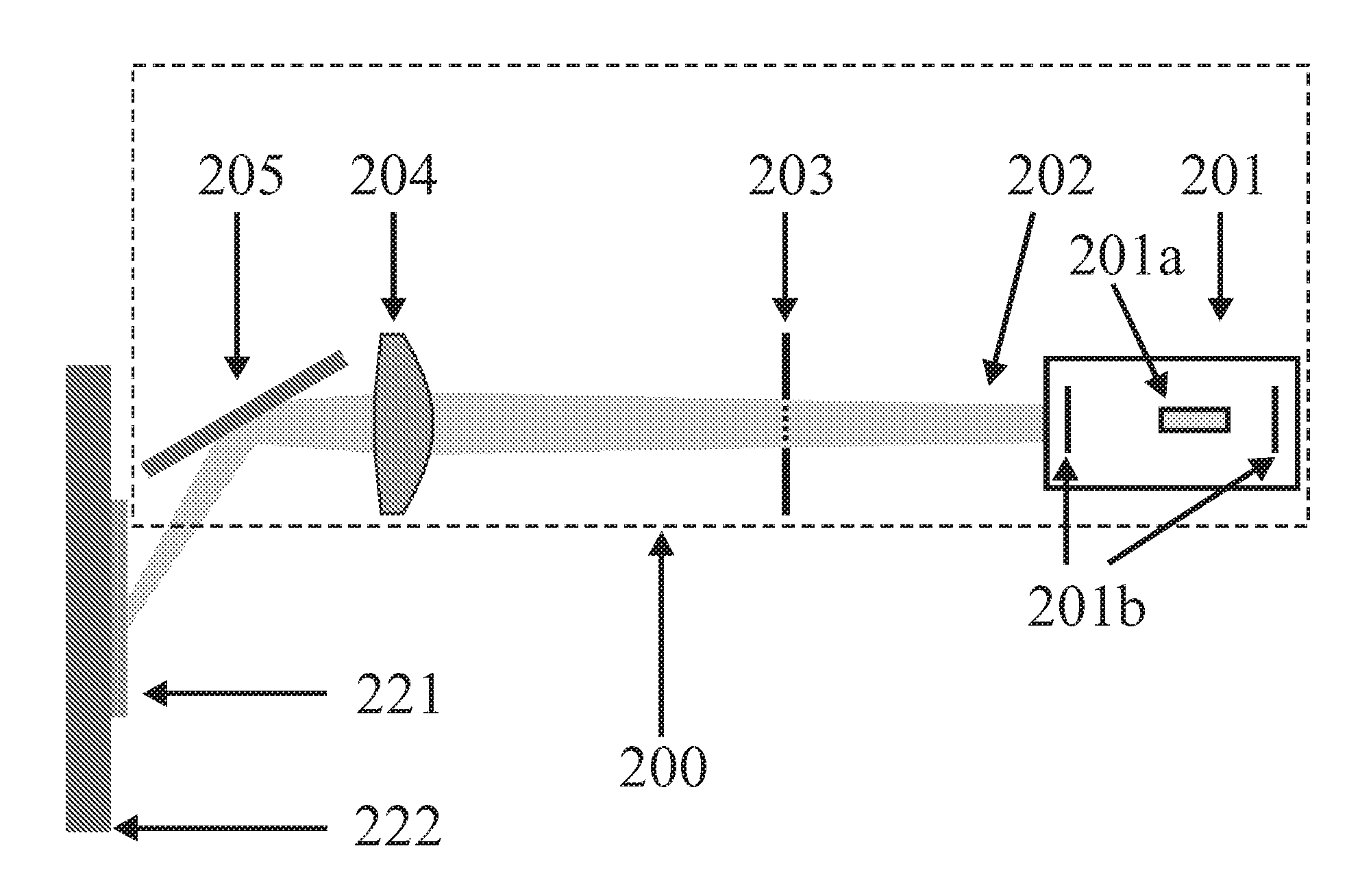
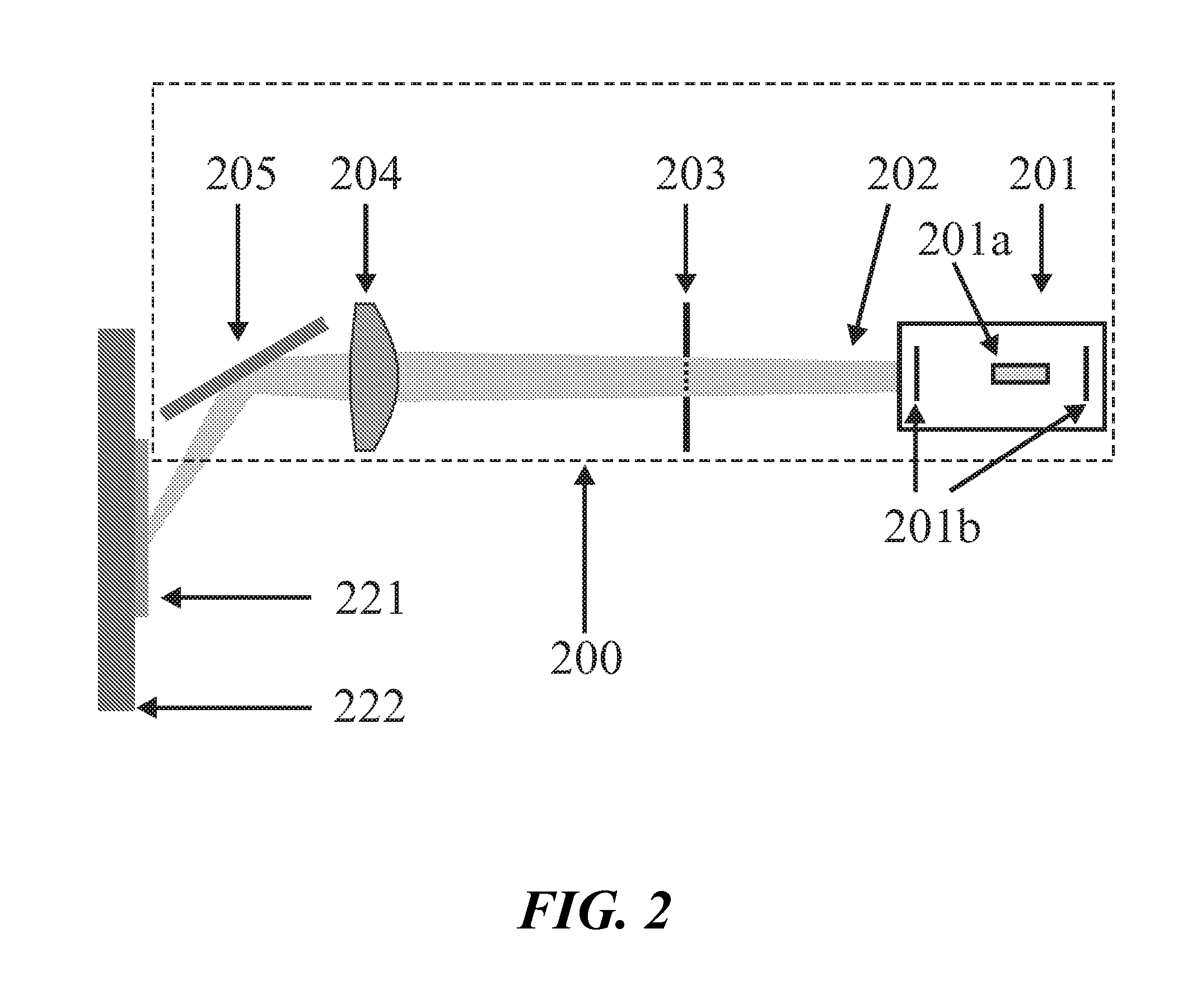
[0048]FIG. 2 illustrates a laser system (200) according to the invention for matrix-assisted laser desorption / ionization in schematic representation. The laser beam (202) is generated in the schematically represented laser unit (201) so as to be temporally pulsed. The set-up required to excite the laser, the laser medium 201a itself, an optical resonator 201b and a variable energy attenuator are located in the laser unit (201). The laser beam (202) illuminates the grid-shaped mask (203), which has a structure comprising orthogonally arranged grid bars within a square aperture. The grid-shaped mask (203) is completely impermeable to the laser beam (202) outside the square aperture and on the grid bars, and increases the spatial modulation of the intensity in the beam profile according to the invention. The lens (204) images the grid-shaped mask (203) via the tilting mirror (205) onto the sample (221).

[0049]Together with other samples not shown, the sample (221) is prepared on a sampl...

second embodiment

[0063]FIG. 5 shows a laser system (500) according to the invention. A pulsed laser beam is generated in the laser unit (501, comprising a laser medium 501a and an optical resonator 501b) and coupled by the lens (502) into an optical fiber (503) (multimode fiber). The fiber output (504) is imaged onto the sample (521) by the lens (505) and the tilting mirror (506).

[0064]In contrast to the prior art, the multimode fiber (503) is not utilized to homogenize the beam profile but, according to the invention, to increase the spatial modulation of the intensity. This requires that the length of the multimode fiber (503) is chosen so that the temporal coherence of the laser beam is greater than the transmission time difference of the transverse fiber modes. In this case, the intensity distribution at the fiber output (504) is no longer given by the superimposition of the intensities of the transverse fiber modes but by the interference of the electromagnetic fields of the individual fiber mo...

third embodiment

[0067]FIG. 6 shows a laser system according to the invention (600). A pulsed laser beam is generated in the laser unit (601), and this beam illuminates a transparent plastic foil (603). The plastic foil (603) has different thicknesses at different places so that the spatial modulation of the phase in the beam profile of the laser beam (602) is increased. As is the case in the other preferred embodiments, the laser medium 601a, the set-up required to excite the laser, an optical resonator 601b and a variable attenuator are located in the laser unit (601).

[0068]If the phase-modulated laser beam (602) can propagate undisturbed, the far-field diffraction image of the plastic foil (603) occurs at a certain distance, and this image has a plurality of irregularly distributed intensity spots. The intensity spots occur as in a speckle pattern because of the random, spatially strongly modulated fluctuations in thickness of the plastic foil (603). However, intensity spots do not form initially...


PUM


Abstract

The invention relates to a laser system for the ionization of a sample by matrix-assisted laser desorption in mass spectrometric analysis. The invention consists in providing a laser system which generates a spatially modulated intensity distribution with intensity spots on the sample, which significantly improves the quality and the robustness of the mass spectrometric analysis compared with a spatially homogeneous intensity distribution and, in particular, improves the ionization efficiency and, for a time-of-flight mass spectrometer with axial injection, the mass resolution and the signal-to-noise ratio.

Description

FIELD OF THE INVENTION[0001]The invention relates to a laser system for the ionization of a sample by matrix-assisted laser desorption in mass spectrometric analysis.BACKGROUND OF THE INVENTION[0002]In the last 10 to 15 years, two methods have prevailed in mass spectrometric analysis for soft ionization of biological macromolecules: Matrix-assisted laser desorption / ionization (MALDI), and electrospray ionization (ESI). The biological macromolecules under analysis will be termed analyte molecules below. With the MALDI method, the analyte molecules are generally prepared on the surface of a sample support in a solid matrix, whereas with the ESI method they are dissolved in a liquid. Both methods have a considerable influence on the mass spectrometric analysis of biological macromolecules in genomics, proteomics and metabolomics; their inventors were awarded the Nobel prize for chemistry in 2002.[0003]In a prepared MALDI sample, there are 103 to 105 times as many matrix molecules as th...

Claims


Application Information

Patent Timeline
Patent Type & Authority Patents(United States)
IPC IPC(8): H01J49/00H01J49/16H01S3/00H01S3/08
CPCH01J49/164H01S3/005H01S3/08022H01J49/161
Inventor HAASE, ANDREASKAYSER, MARKUSHOHNDORF, JENSHOLLE, ARMIN
Owner BRUKER DALTONIK GMBH & CO KG
Why Eureka
Try Eureka