High brightness LED apparatus with an integrated heat sink

a heat sink and led technology, applied in lighting and heating apparatus, semiconductor devices for light sources, semiconductor/solid-state device details, etc., can solve problems such as hazard or damage, unexpected damage to other parts adjacent to led apparatus, and inability to produce sufficient light for illumination, etc., to prolong the useful life of leds and enhance illumination. brightness

Inactive Publication Date: 2007-06-26
EXCEL CELL ELECTRONICS
View PDF27 Cites 167 Cited by
  • Summary
  • Abstract
  • Description
  • Claims
  • Application Information

AI Technical Summary

Benefits of technology

[0008]The main objective of the invention is to provide an LED apparatus with an integrated heat sink and at least one LED for illumination, each of the at least one LED has multiple dies inside to enhance illuminative brightness and the heat sink will keep the LEDs from brightness decay and extend the useful life of the LEDs.
[0009]An LED apparatus with an integrated heat sink includes a heat sink base and at least one LED mounted in the heat sink base. The heat sink base includes a substrate and multiple dissipating fins formed integrally on the substrate. Each of the at least one LED includes a body and multiple dies. The body is mounted in the substrate and includes a conductive seat with a top recess. The dies are mounted on the conductive seat in the top recess and produce a great amount of light beams for enhanced brightness of illumination. The dissipating fins efficiently dissipate heat produced by the at least one LED to prevent each LED from brightness decay and extend the useful life of each LED.

Problems solved by technology

Using a single die in one single LED cannot produce sufficient light for illumination.
Unless the accumulated heat from the illuminative apparatus is removed quickly and efficiently, the illuminative apparatus may cause a hazard or damage.
If the heat produced by the LEDs cannot be efficiently dissipated, the accumulated heat may cause unexpected damage to or influence normal operations of other parts adjacent to the LED apparatus.

Method used


Image

  • High brightness LED apparatus with an integrated heat sink
  • High brightness LED apparatus with an integrated heat sink
  • High brightness LED apparatus with an integrated heat sink

Examples


first embodiment

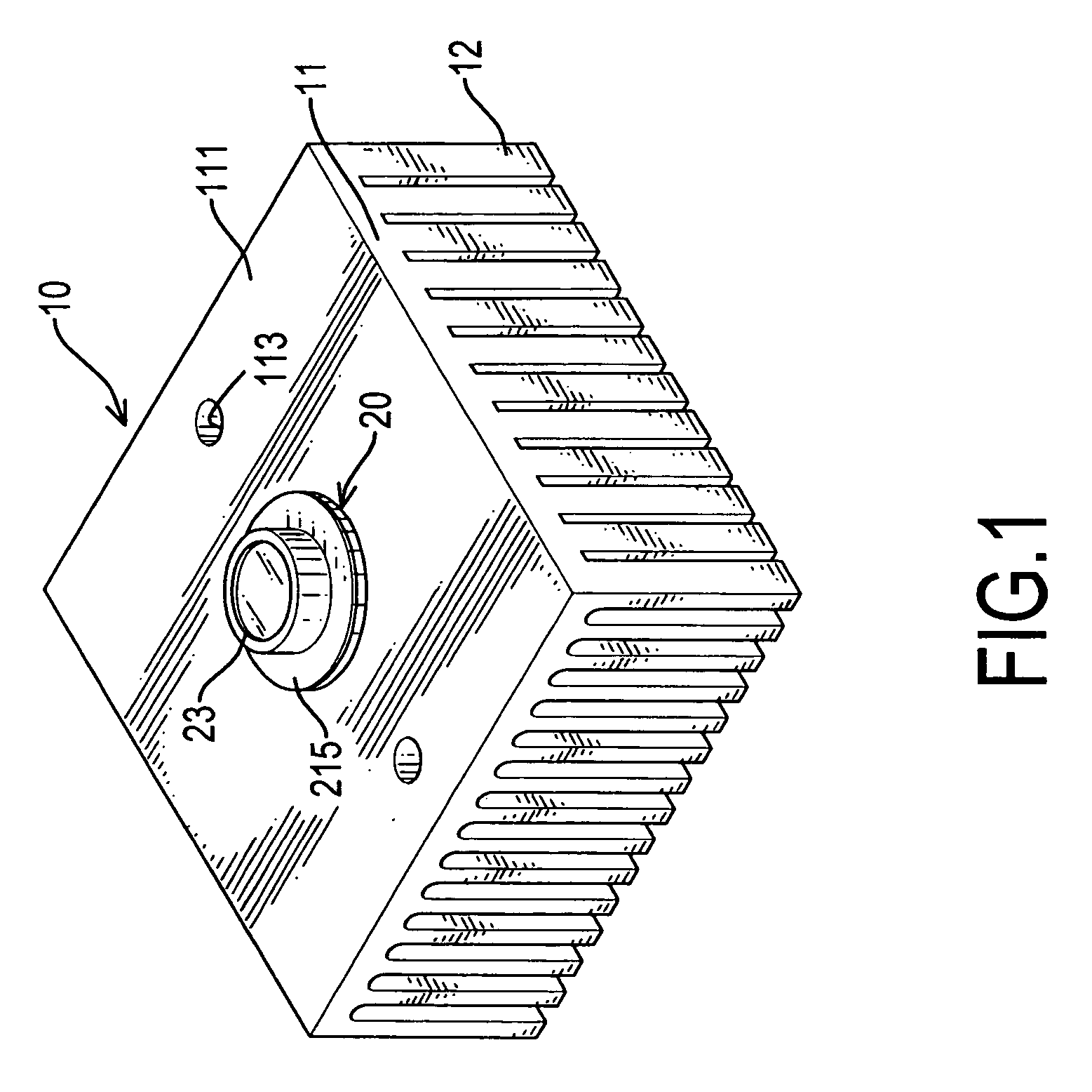
[0017]With reference to FIGS. 1 and 4, a high brightness LED apparatus with an integrated heat sink in accordance with the present invention comprises a heat sink base (10) and an LED (20).

[0018]The heat sink base (10) is made of the high thermal conductivity materials and comprises a substrate (11) and multiple integrated dissipating fins (12). The substrate (11) is a planar block and has a first surface (111), a second surface (112), multiple mounting holes (113) and an LED hole (114). The first surface (111) is opposite to the second surface (112). The holes (113, 114) are defined completely through the substrate (11). The dissipating fins (12) are formed and arranged on the entire second surface (112) of the substrate (11).

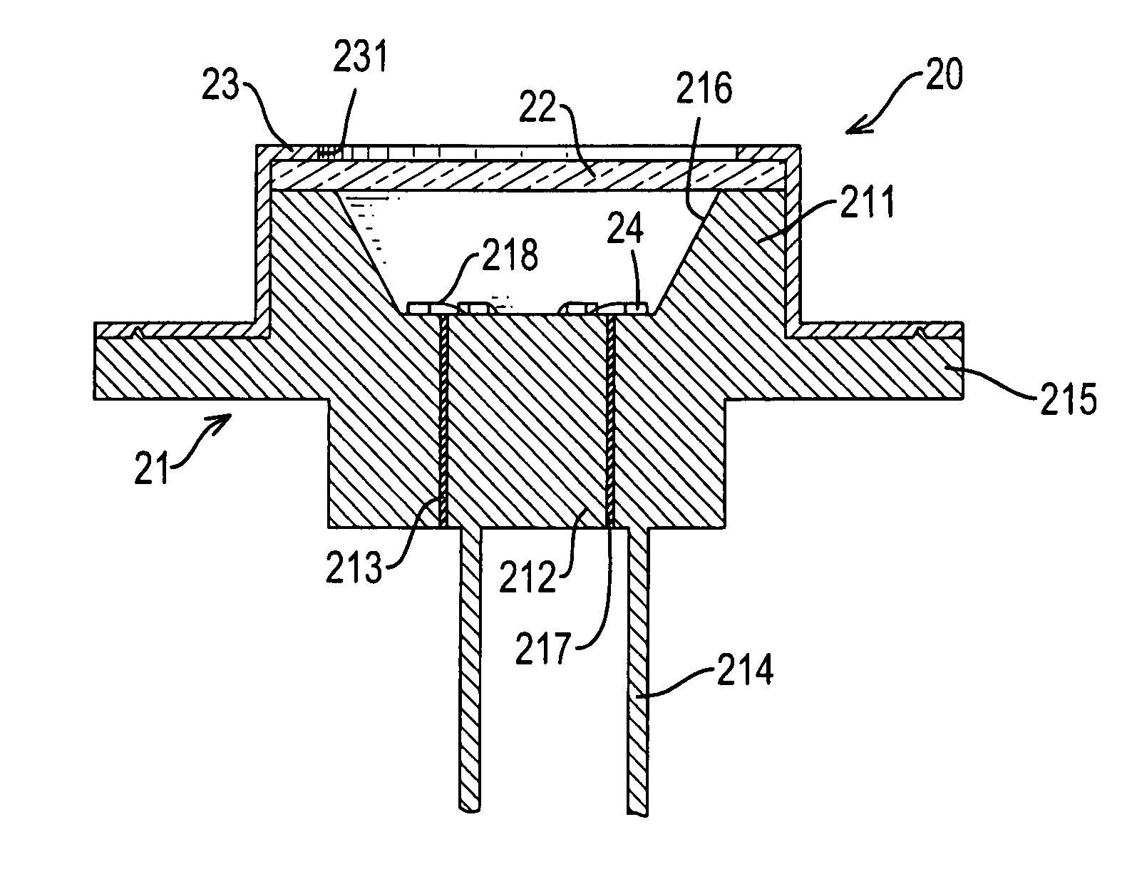
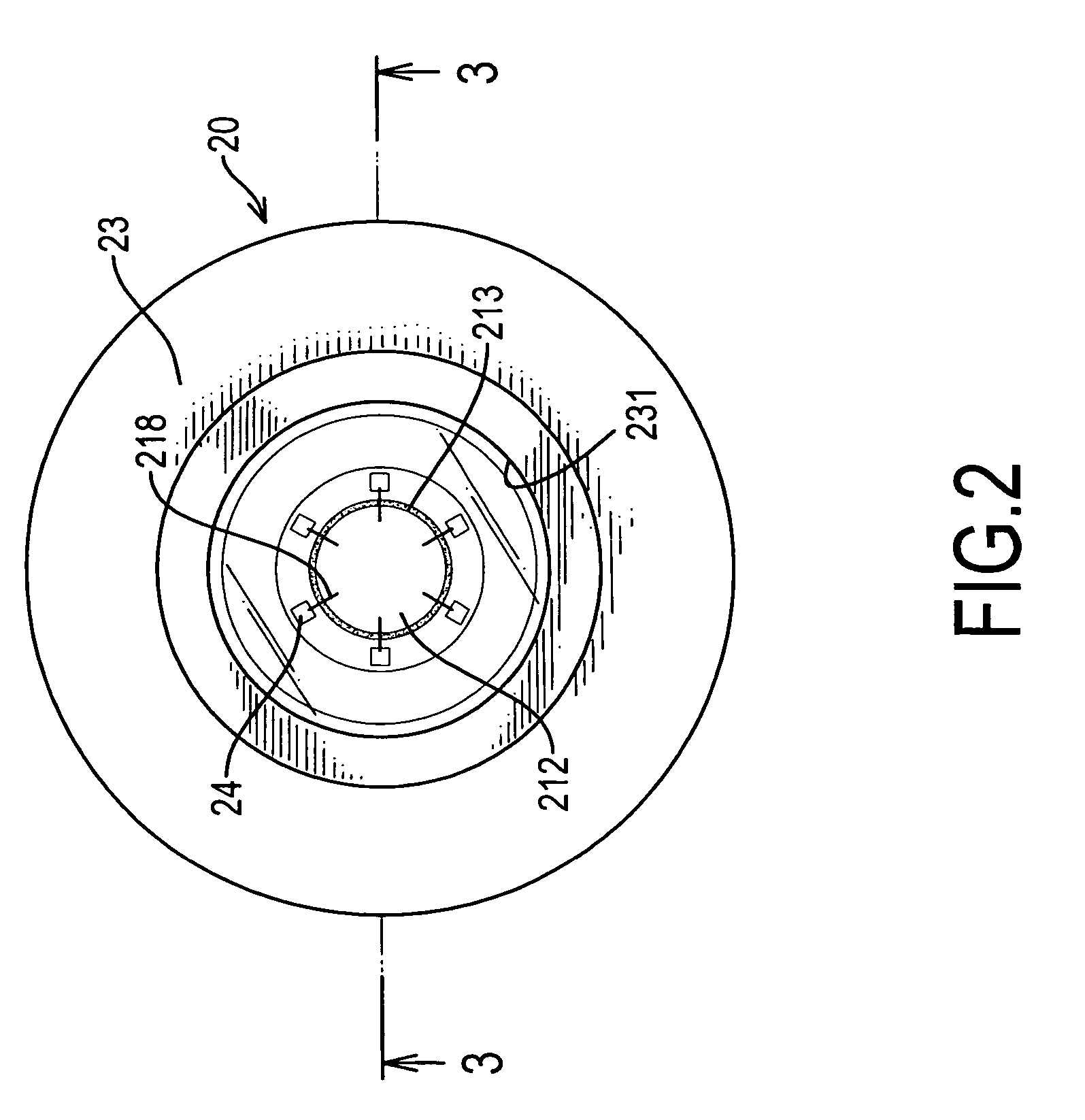
[0019]With reference to FIGS. 2, 3 and 4, the LED (20) is mounted and held in the LED hole (114) in the substrate (11) and comprises a body (21), a cover (22), an outside casing (23) and multiple dies (24).

[0020]The body (21) is held in the LED hole (114) and ...

second embodiment

[0025]With reference to FIG. 5, the LED apparatus comprises a heat sink base (10′) and multiple LEDs (20). The heat sink base (10′) has a thin disk substrate (11′) and multiple dissipating fins (12′). The substrate (11′) has a first surface (111′), a second surface, an annular edge, a mounting hole (113′), and multiple LED holes (114′). The first surface (111′) is opposite to the second surface. The holes (113′, 114′) are defined completely through the substrate (11′). The LEDs (20) are respectively mounted in the LED holes (114′).

[0026]The dissipating fins (12′) are integrally formed on the second surface along the annular edge of the substrate (11′) by bending or forging to dissipate the heat.

third embodiment

[0027]With reference to FIG. 6, the LED apparatus comprises a heat sink base (10″) and multiple LEDs (20). The heat sink base (10″) has a thin disk substrate (11″) and multiple dissipating fins (12″). The substrate (11″) has a first surface, a second surface (112″), an annular edge and multiple LED holes. The first surface is opposite to the second surface (112″).

[0028]The dissipating fins (12″) are integrally formed on the second surface (112″) along the annular edge of the substrate (11′) by bending or forging and are arranged complementarily relative to each other to dissipate the heat.

[0029]Consequently, each of the LEDs (20) that has multiple dies (24) will produce high brightness for illumination. The dissipating fins (12, 12′, 12″) of the heat sink bases (10, 10′, 10″) will improve the performance of dissipating the heat produced by the LEDs (20). The heat will not easily accumulate around the entire LED apparatus. The LEDs (20) of the LED apparatus can produce light to brigh...


PUM


Abstract

A high brightness LED apparatus with an integrated heat sink includes a heat sink base and at least one LED mounted in the heat sink base. The heat sink base includes multiple dissipating fins formed integrally on the substrate. Each of the at least one LED includes a body and multiple dies. The body is mounted in the substrate and includes a conductive seat with a top recess. The dies are mounted on the conductive seat in the top recess and produce a great amount of light beams for an enhanced brightness of illumination. The dissipating fins will efficiently dissipate heat produced by the at least one LED to prevent each LED from brightness decay and extend the useful life of each LED.

Description

BACKGROUND OF THE INVENTION[0001]1. Field of the Invention[0002]The present invention relates to a light emitting diode (LED) apparatus, and more particularly to a high brightness LED apparatus with an integrated heat sink so that the LED apparatus will produce high performance brightness and dissipate efficiently heat accumulated in the LED apparatus while the LED apparatus produces light.[0003]2. Description of Related Arts[0004]Light emitting diodes (LEDs) have been extensively used for illumination and visible indicator purposes. A light emitting diode comprises generally a single die and two conductive leads. The leads connect to the die to establish a path of transmitting electricity so that the die will produce light beams as the electricity drives the die.[0005]Using a single die in one single LED cannot produce sufficient light for illumination. An LED apparatus as being an illuminative apparatus generally comprises a great quantity of LEDs to create bright illuminations. H...

Claims


Application Information

Patent Timeline
Patent Type & Authority Patents(United States)
IPC IPC(8): H05K7/20F21V7/00
CPCF21K9/00F21V29/004F21V29/2212H01L25/0753F21V29/80F21V29/773F21V29/74F21V29/745F21Y2101/02H01L33/647H01L2924/0002H01L2924/00F21V29/70F21V29/763F21Y2115/10
Inventor CHEN, AN-SI
Owner EXCEL CELL ELECTRONICS
Why Eureka
Try Eureka