Implantable leadless cardiac device with flexible flaps for sensing

a leadless cardiac and flexible technology, applied in the field of implantable leadless cardiac sensing devices, can solve the problems of lead complications even greater, life-threatening perforations of the great vessels and hearts, and the use of transvenous lead systems, despite their many advantages, are not without chronic patient management limitations, and are not without complications

Inactive Publication Date: 2007-06-26
PACESETTER INC
View PDF22 Cites 117 Cited by
  • Summary
  • Abstract
  • Description
  • Claims
  • Application Information

AI Technical Summary

Benefits of technology

[0008]The implantable cardiac device may include one, two, or more flexible flap extensions. The device is inserted through a single incision. Each flap contains one or more sensors incorporated into it.

Problems solved by technology

The requirement for pacemakers and ICDs to use intravenous catheters and transvenous leads is an impediment to very long term management as most individuals will begin to develop complications related to lead system malfunction sometime in the 5–10 year time frame, often earlier.
In addition, chronic transvenous lead systems, their reimplantation and removals, can damage major cardiovascular venous systems and the tricuspid valve, as well as result in life threatening perforations of the great vessels and heart.
Consequen

Method used


Image

  • Implantable leadless cardiac device with flexible flaps for sensing
  • Implantable leadless cardiac device with flexible flaps for sensing
  • Implantable leadless cardiac device with flexible flaps for sensing

Examples


Embodiment Construction

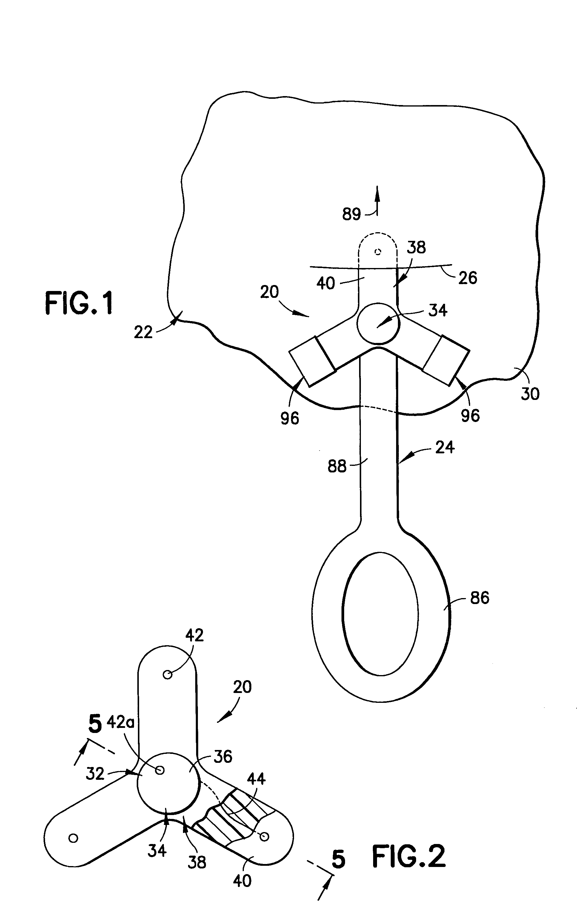
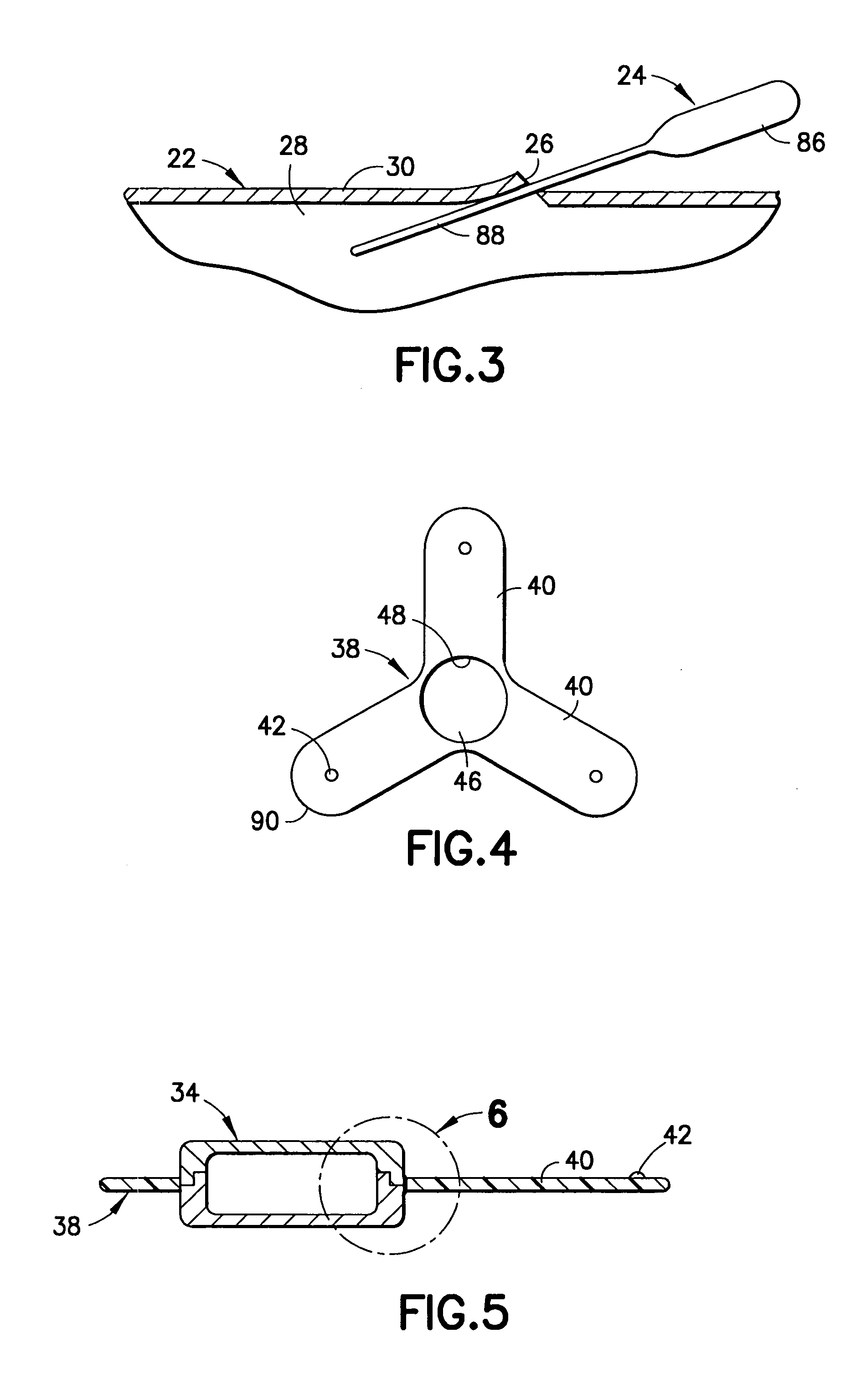
[0028]Referring now to FIGS. 1 and 2, there is illustrated in top plan views, respectively, sensing apparatus 20 intended for subcutaneous implantation into a body 22. In FIG. 1, the sensing apparatus 20 has been reconfigured in a manner to be explained from its FIG. 2 form, and with the aid of a tool 24, is being inserted through an incision 26 into a cavity 28 (FIG. 3) beneath skin 30 of the body 22.

[0029]Although the present invention will be described with reference to the embodiments shown in the drawings, it should be understood that the present invention can be embodied in many alternate forms or embodiments. In addition, any suitable size, shape or type of elements or materials could be used.

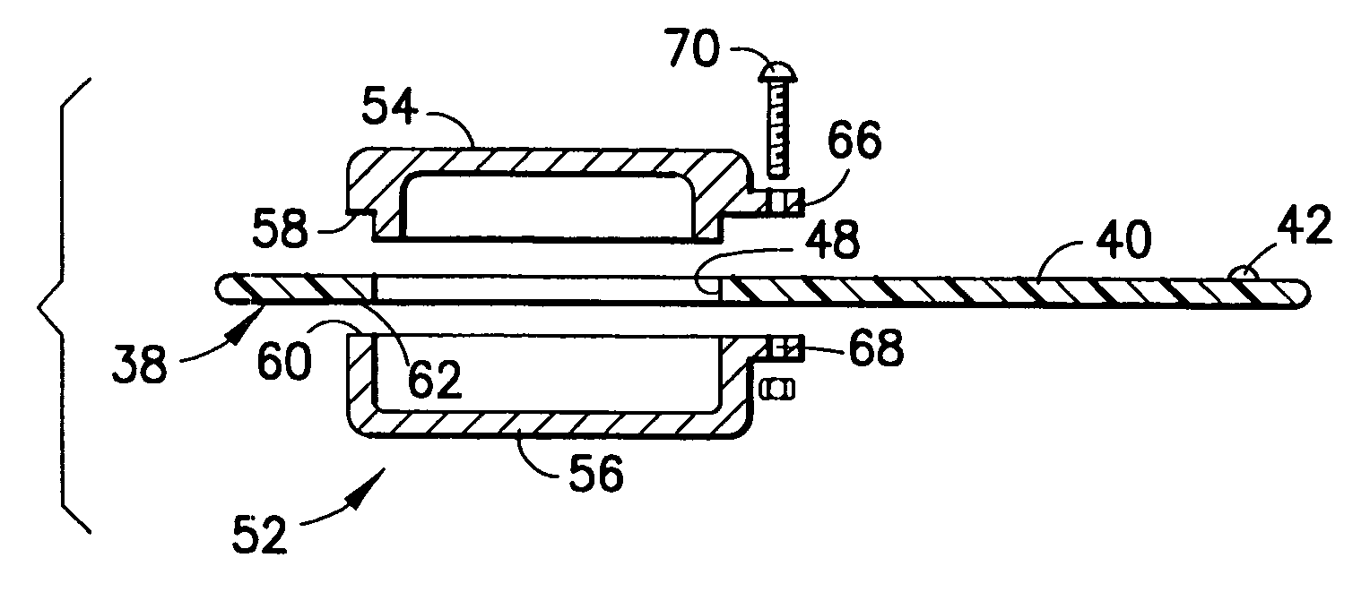
[0030]The sensing apparatus 20 includes an electrical stimulator device 32 such as a pacemaker or an implantable cardioverter defibrillator (ICD) which is encased in a housing 34 having an outer peripheral surface 36. A flap member 38 of flexible insulative sheet material is mounted on t...


PUM


Abstract

A technique for performing sensing operations in the body subcutaneously employs, in combination, the housing of an electrical stimulator such as a pacemaker or an implantable cardioverter defibrillator and an integral flap member of flexible insulative sheet material which has at least one arm projecting away therefrom to an extreme tip end. Each arm is rolled about itself from the tip end on a lateral axis transverse of the longitudinal axis of the arm into a compact unit adjacent the housing. An incision is made through the skin and a region beneath the skin enlarged to form a cavity. The compact unit is then inserted into the cavity and unrolled about the lateral axis of each arm so as to be laid flat under the skin. When positioned into a desired orientation, each flap member is sutured to the skin to maintain the desired orientation.

Description

FIELD OF THE INVENTION[0001]The present invention relates to implantable leadless cardiac sensing device which does not require transvenous placement.BACKGROUND OF THE INVENTION[0002]The requirement for pacemakers and ICDs to use intravenous catheters and transvenous leads is an impediment to very long term management as most individuals will begin to develop complications related to lead system malfunction sometime in the 5–10 year time frame, often earlier. In addition, chronic transvenous lead systems, their reimplantation and removals, can damage major cardiovascular venous systems and the tricuspid valve, as well as result in life threatening perforations of the great vessels and heart. Consequently, uses of transvenous lead systems, despite their many advantages, are not without their chronic patient management limitations in those with life expectancies of more than five years. The problem of lead complications is even greater in children where body growth can substantially a...

Claims


Application Information

Patent Timeline
IPC IPC(8): A61N1/372
CPCA61N1/05A61N1/375A61N1/3752A61N1/3756A61N1/37512A61N1/37518
Inventor FARAZI, TARANEH GHAFFARIFALKENBERG, ERIC
Owner PACESETTER INC
Why Eureka
Try Eureka