Smart card and method for manufacturing a smart card

a smart card and manufacturing method technology, applied in the field of smart cards and manufacturing methods, can solve the problems of reducing the size and number of electronic components of the holding device, affecting the body of the relatively large holding device, and causing deformations

Inactive Publication Date: 2007-07-03
CARDXX
View PDF32 Cites 84 Cited by
  • Summary
  • Abstract
  • Description
  • Claims
  • Application Information

AI Technical Summary

Benefits of technology

[0054]The present invention has several advantages including a cost effective manner to produce one or more smart cards. Most of the modules in the smart card 1 can be constructed in a traditional manner that reduces manufacturing costs. Further, the printed circuit board 10 and filler board construction 30 enable greater protection to circuit components 20 during manufacturing which in turn lowers production costs and raises production output. Moreover, the method of the present invention can be easily adapted to produce multiple smart cards at once.

Problems solved by technology

The use of relatively large, mechanical holding devices having hard, sharply defined, bodies to hold their electronic components in place during injection of such thermosetting materials has, however, created certain problems.
For example, the bodies of these relatively large holding devices (i.e., large relative to the electronic components they hold) are often adversely affected by those shock, flexure and / or torsion forces the card may encounter in normal (and abnormal) use.
This positioning limitation usually cuts down on the size and number of electronic components that can be placed in such cards.
Moreover, due to differences in the coefficient of expansion of the materials used to make these relatively large holding devices—relative to the coefficient of expansion of the other elements of such cards—deformations often appear on the external surfaces of finished cards that contain such electronic component holding devices.
However, the use of such glues to secure these holder devices has produced another set of problems.
Primarily, the disclosed method produces warping and other undesirable physical defects caused by the curing of thermosetting material.
Further, this method is suitable only for cards having one or two components, thus limiting its functionality.
'054 creates defects such as voids and air bubbles within a smart card because the geometric shapes of the electronic components within the card obstruct the flow of the thermosetting material such that the thermosetting material flows around the components faster than the air can be pushed out of the core of the smart card.
'054 requires the use of custom equipment, significantly limiting the scope and scalability of its application.

Method used


Image

  • Smart card and method for manufacturing a smart card
  • Smart card and method for manufacturing a smart card
  • Smart card and method for manufacturing a smart card

Examples


Embodiment Construction

[0027]Embodiments of the present invention will be described below with reference to the accompanying drawings. It should be understood that the following description is intended to describe exemplary embodiments of the invention, and not to limit the invention.

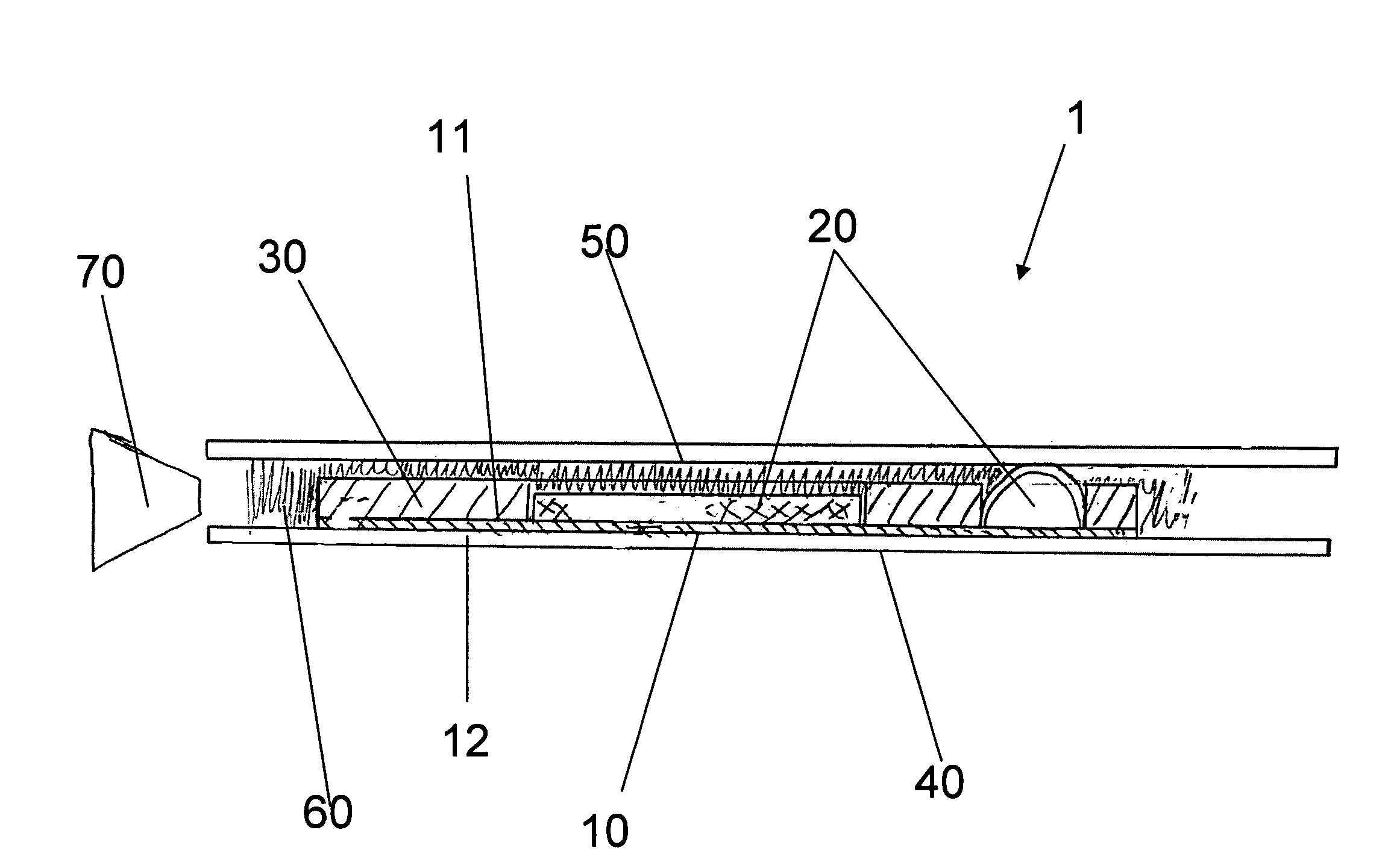
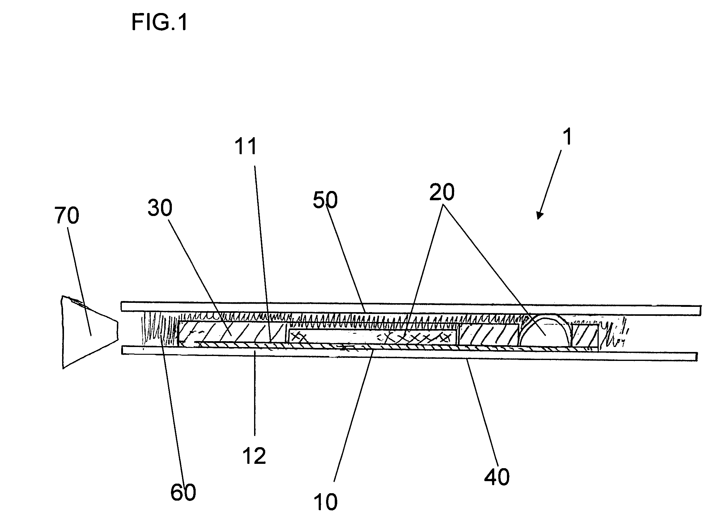
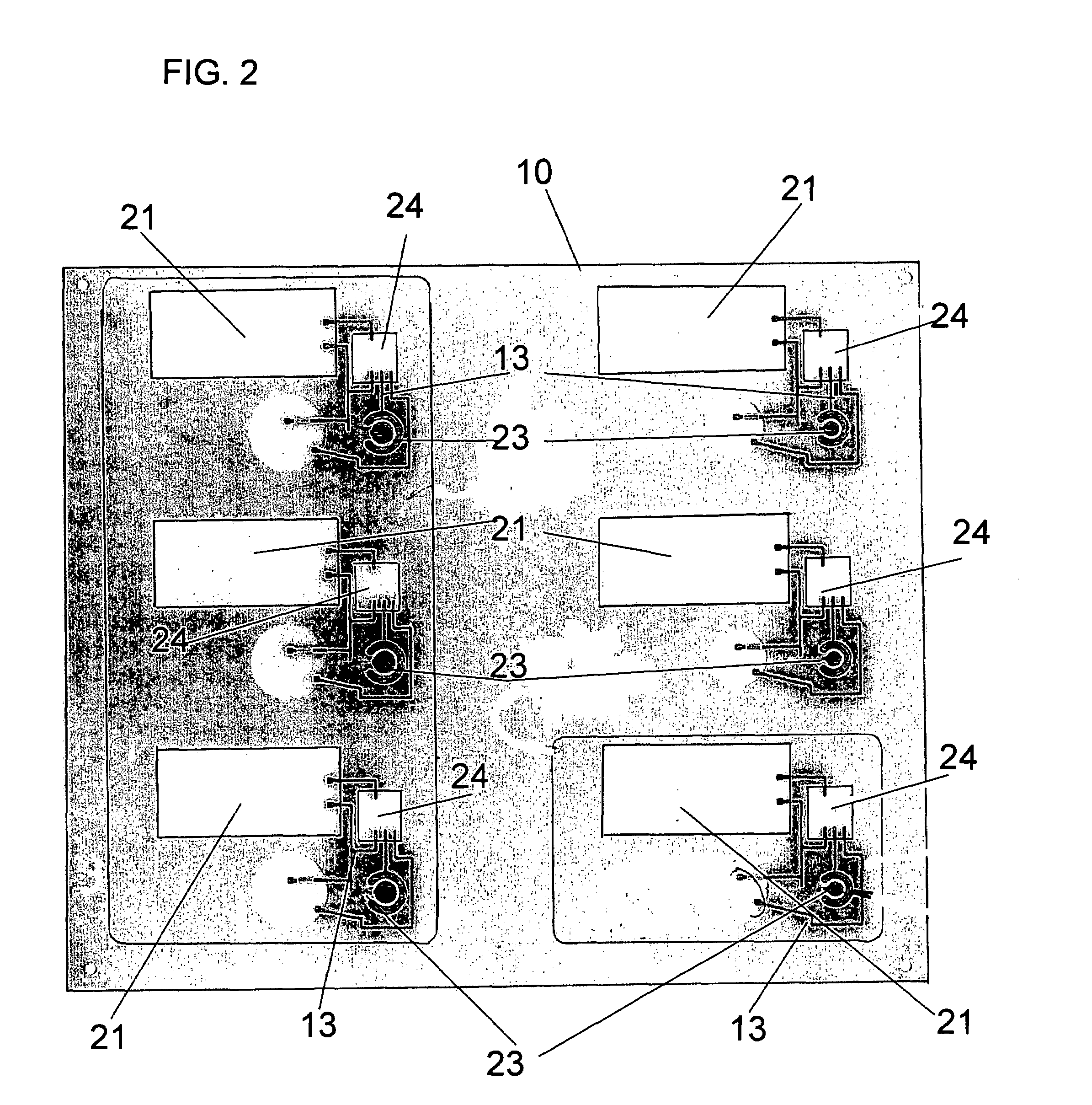
[0028]According to one embodiment of the present invention, as shown in FIG. 1, the smart card 1 comprises a printed circuit board 10, a plurality of circuit components 20, a filler board 30, a bottom overlay 40, a top overlay 50 and a core layer 60.

[0029]The printed circuit board has a top surface 11 and a bottom surface 12. The printed circuit board is comprised of any known conventional material suitable for receiving an electronic circuit. For example, the printed circuit board may be comprised of a flame retardant laminate with a woven glass reinforced epoxy resin. This material is also known as FR-4 board. Alternatively, the printed circuit board may be comprised of a plastic compound that is suitable for receiving cond...


PUM

PropertyMeasurementUnit
thicknessaaaaaaaaaa
thicknessaaaaaaaaaa
thicknessaaaaaaaaaa

Abstract

A smart card and a method for manufacturing the same wherein the smart card is composed of a printed circuit board, having a top surface and a bottom surface, a plurality of circuit components attached to the top surface of the printed circuit board, a filler board, attached to the top surface of the printed circuit board, a bottom overlay attached to the bottom surface of the printed circuit board, a top overlay positioned above the top surface of the printed circuit board and a thermosetting polymeric layer positioned between the top surface of the printed circuit board and the top overlay.

Description

BACKGROUND OF THE INVENTION[0001]Generally, smart cards may be used as credit cards, bankcards, ID cards, telephone cards, security cards or similar devices. Smart cards are generally constructed by assembling several layers of plastic sheets in a sandwich array. Further, smart cards contain electronic components that enable the smart card to perform a number of functions.[0002]European Patent 0 350 179 discloses a smart card wherein electronic circuitry is encapsulated in a layer of plastic material that is introduced between the card's two surface layers. The method further comprises abutting a high tensile strength holding member against a side of a mould, locating the smart card's electronic components with respect to that side and then injecting a reaction moldable polymeric material into the mould such that it encapsulates the electronic components.[0003]European Patent Application 95400365.3 teaches a method for making contact-less smart cards. The method employs a rigid fram...

Claims


Application Information

Patent Timeline
Patent Type & Authority Patents(United States)
IPC IPC(8): G06K19/06B29C45/14G06K19/02H01R43/00H05K3/30
CPCG06K19/0702G06K19/07345G06K19/07724G06K19/07745H05K3/284H01H2203/038H01H2231/05Y10T29/49146H05K2203/0186H05K2203/1316H01L2924/0002Y10T29/49121H01L2924/00G06K19/07G06K19/077
Inventor SINGLETON, ROBERT
Owner CARDXX
Why Eureka
Try Eureka