Cutting plate for rotating tools

a technology of cutting plate and tool, which is applied in the direction of turning apparatus, boring/drilling apparatus, reaming tools, etc., can solve the problems of increasing the friction between the tools, overloading the machine and/or the tools, and poor guiding

Inactive Publication Date: 2007-07-03
KOMET GROUP GMBH
View PDF18 Cites 23 Cited by
  • Summary
  • Abstract
  • Description
  • Claims
  • Application Information

AI Technical Summary

Problems solved by technology

When the circular grinding has a radius which is too small, the guiding becomes relatively poor.
When approaching the bore radius there occurs a surface contact, which increases the friction between the tool and the bore, and which can result in overloads on the machine and / or the tools.
The more cutting edges that are arranged over the circumference of the tool, the more serious this effect becomes.

Method used


Image

  • Cutting plate for rotating tools
  • Cutting plate for rotating tools
  • Cutting plate for rotating tools

Examples


Embodiment Construction

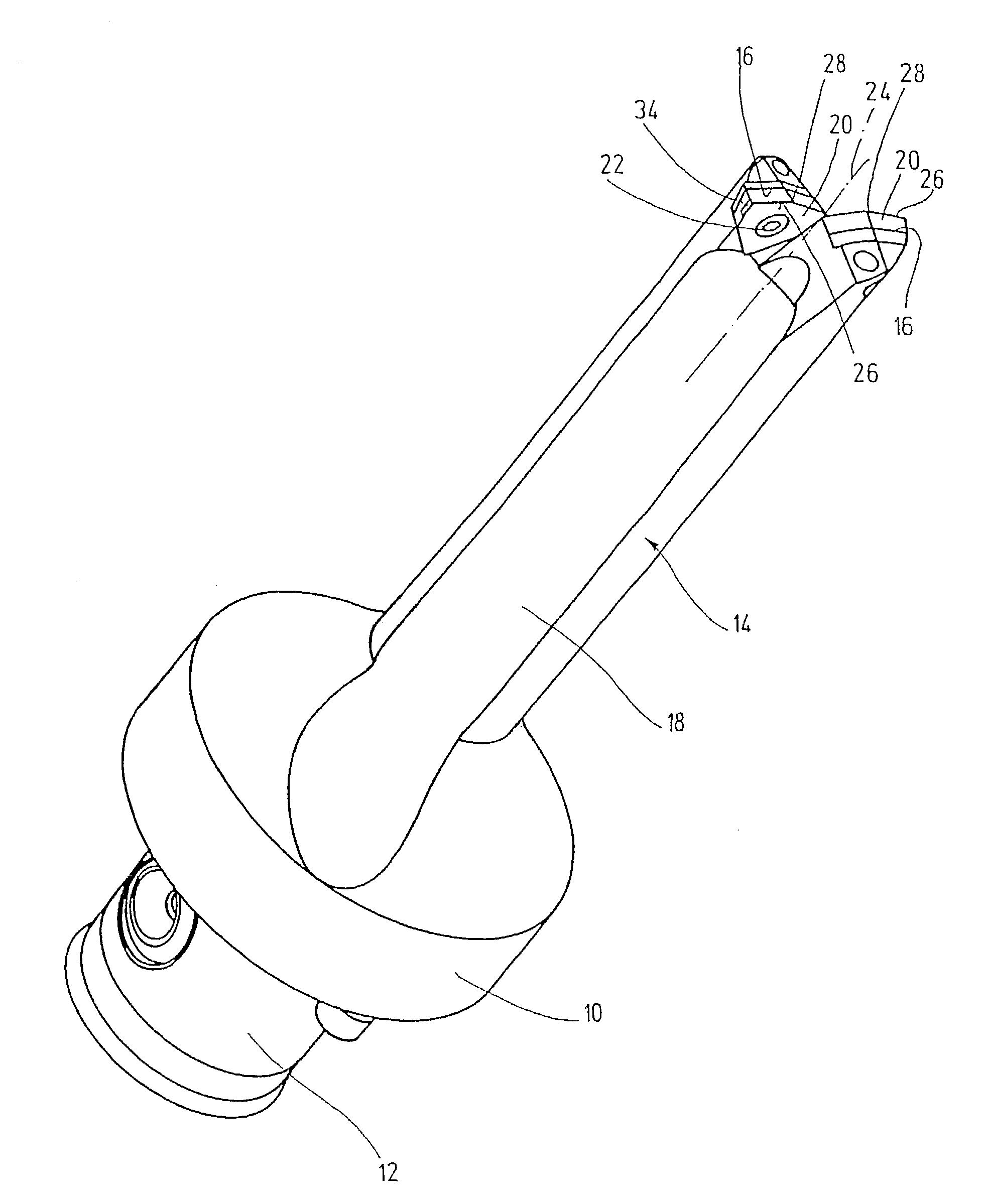
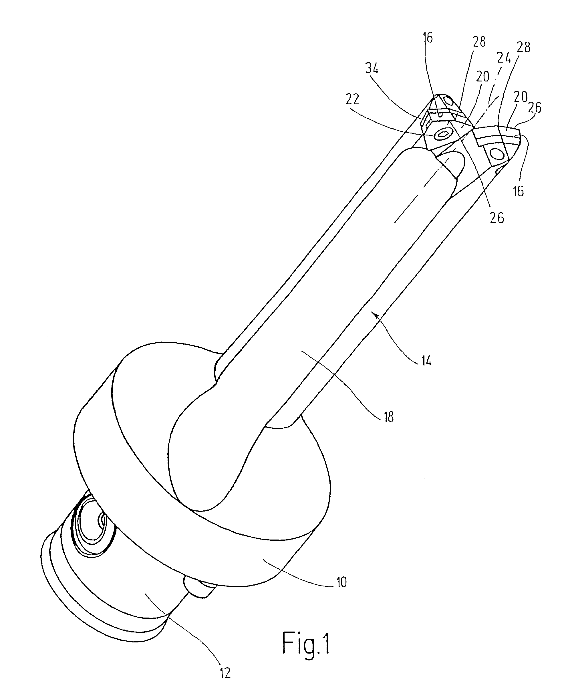
[0013]The boring tool illustrated in the drawings is designed as a core drill with double cutting edges. The boring tool is designated for use in machine tools and has for this purpose a coupling shaft 12 for connection to a not illustrated tool spindle, which coupling shaft 12 is defined by a coupling flange 10 for a plane-surface bearing. An elongated base body 14 is also connected to the coupling flange 10, which base body 14 has in the area of its face-side end two plate seats 16, from where chip-conveying grooves 18 extend over the length of the base body 14. Two trigon indexable inserts or cutting plates 20, which are designed alike, are exchangeably arranged in the plate seats 16 and are secured on the base body 14 by fastening screws 22. The fastening screws are thereby screwed into the base body 14 starting out from the chip-conveying grooves essentially perpendicularly with respect to the drill axis 24.

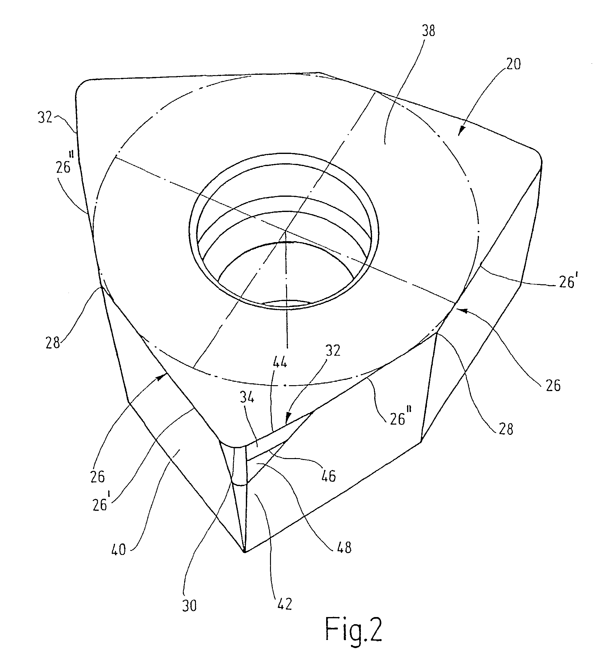
[0014]Each of the cutting plates has three major cutting edges 26, of w...


PUM

PropertyMeasurementUnit
lengthaaaaaaaaaa
angleaaaaaaaaaa
point angleaaaaaaaaaa

Abstract

A cutting plate for rotating tools includes a major cutting edge connected to a minor cutting edge in a radial extension thereof over a cutting corner. A common face joins a longitudinal side of the major cutting edge and the minor cutting edge, while a major flank or a minor flank joins the other side of the major and minor cutting edges. The flank face form a wedge angle The tool is supported on a boring wall with low friction to enable vibration-free machining. A support land near the minor cutting edge has two interspaced support edges. The support edges have the same radial distance from the tool axis over their entire length. The support edges are oriented parallel to the tool axis and the support land has a flat surface parallel to the tool axis.

Description

FIELD OF THE INVENTION[0001]The invention relates to a cutting plate for tools rotating about a tool axis, in particular for boring tools with several cutting edges, comprising a major cutting edge and a minor cutting edge, which is connected, in the extension of said major cutting edge radially outwardly through a plate corner, at an angle to said major cutting edge, comprising a common machining surface connected on one longitudinal side of the major cutting edge and of the minor cutting edge, and comprising one major flank or minor flank connected to the other longitudinal side of the major cutting edge or the minor cutting edge, and defining a wedge angle with the common machining face.BACKGROUND OF THE INVENTION[0002]In order to avoid vibrations during operation in far projecting tools with several cutting edges and with cutting plates of the aforementioned type, a minor cutting edge designed as a guiding edge is provided which is guided along the bore wall. In order to achieve...

Claims


Application Information

Patent Timeline
Patent Type & Authority Patents(United States)
IPC IPC(8): B23B51/02B23B51/00B23B27/14
CPCB23B27/145B23B2200/0419Y10T408/868Y10T407/23Y10T408/909B23B2200/201
Inventor LEUZE, PETERROESER, FRANK
Owner KOMET GROUP GMBH
Why Eureka
Try Eureka