Check patentability & draft patents in minutes with Patsnap Eureka AI!

Offshore windmill electric generators

a technology for electric generators and offshore windmills, applied in machine supports, machines/engines, liquid fuel engines, etc., can solve the problems of vibration of the structure, the addition of installation cost of the structure is of paramount importance, and the problem of another problem with the electric generators of offshore windmills

Inactive Publication Date: 2007-07-03
GRAND VENT POWER
View PDF9 Cites 11 Cited by
  • Summary
  • Abstract
  • Description
  • Claims
  • Application Information

AI Technical Summary

Benefits of technology

The solution effectively reduces vibration transmission and maintains the structural levelness, enhancing operational efficiency and reducing maintenance needs by minimizing wear and tear on the wind turbine components.

Problems solved by technology

Therefore, the machines can be mounted in remote locations and can operate trouble free for extended periods of time.
Consequently, the additional cost of installation in providing the structure is of paramount importance.
While the offshore support structure can be generally constructed as well known in the offshore oil industry and specifically as described in U.S. Pat. No. 4,260,291, two problems have generally developed in connection with the generation of the electric power at these offshore facilities.
One such problem is vibration of the structure caused by the wind itself acting upon the structure and the rotation of the windmill blades to turn the generator to develop the electric power.
Another problem exists with respect to the offshore windmill electric generators.
This causes uneven forces to be present during operation creating additional wear and tear and resulting inefficiencies, if not a major reconstruction adjustment of the windmill involved.

Method used


Image

  • Offshore windmill electric generators
  • Offshore windmill electric generators
  • Offshore windmill electric generators

Examples


Embodiment Construction

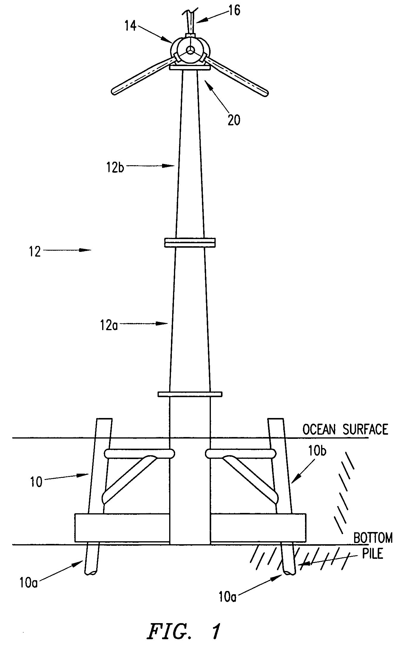
[0023]The installation costs must also be controlled to allow economic benefit to this operation. Therefore, in considering transportation, lifting, assembly, weather conditions, and other factors a lift boat unit appears to be the most economical method by which the installation of the windmill assembly can be accomplished. Lift boats have been used in offshore oil production for years and can operate in water depths of six feet through 200 feet and are also used to erect windmill structure. The lift boat has three or four legs for stability on which the structure is lifted out of the water to the height desired adjacent to the windmill structure for stability purposes. The lift boat would carry the parts the structure to the site and use rotating cranes of about 150-ton capacity to assemble the structure.

[0024]In order to facilitate the assembly of the tower assembly and nacelle generating pod, a work platform is required. A work platform is mounted to cantilever beams which can b...


PUM


Abstract

The described invention involves the windmill generation of electric power, particularly from offshore windmill generators. The invention involves inserting an adapter between the nacelle of the windmill and the tower, which includes either a leveling device or a vibration dampening device, or both.

Description

CROSS REFERENCE TO RELATED APPLICATIONS[0001]This application claims the benefit of U.S. Provisional Application No. 60 / 569,077, filed May 6, 2004.FEDERALLY SPONSORED RESEARCH[0002]Not applicable.REFERENCE TO MICROFICHE APPENDIX[0003]Not applicable.FIELD OF THE INVENTION[0004]This invention relates generally to the structure for the generation of electric power using a wind turbine, particularly wind turbines erected in an offshore environment.[0005]The quest for alternative energy sources is a global priority. One source of electric power is wind energy. Throughout the world, wind patterns exist. In prior years, small wind generating systems were developed in which high wind velocities were required. Also the elevation of the wind systems was mounted quite low failing to take advantage of wind velocities, which are increased above the surface of the earth. In recent years, more efficient and larger wind machines have been developed. These machines operate efficiently at low wind ve...

Claims


Application Information

Patent Timeline
Patent Type & Authority Patents(United States)
IPC IPC(8): F03D7/06F03D11/04F16M13/00F16M7/00
CPCF03D11/04F16M7/00F05B2240/95F05B2260/96Y02B10/30Y02E10/727E02B17/027E02B2017/0065E02B2017/0091F03D13/25Y02E10/72
Inventor SCHELLSTEDE, HERMAN J.
Owner GRAND VENT POWER
Features
  • R&D
  • Intellectual Property
  • Life Sciences
  • Materials
  • Tech Scout
  • Unparalleled Data Quality
  • Higher Quality Content
  • 60% Fewer Hallucinations
Learn More