Power distribution system and control system for same

a power distribution system and control circuit technology, applied in the direction of switch power arrangement, emergency power supply arrangement, contact mechanism, etc., can solve the problems of inability to withstand a long interruption of electric power, and the inability to connect two power sources to the load at the same tim

Inactive Publication Date: 2007-07-03
EATON INTELLIGENT POWER LTD
View PDF9 Cites 35 Cited by
  • Summary
  • Abstract
  • Description
  • Claims
  • Application Information

AI Technical Summary

Problems solved by technology

Alternate power sources are provided for any number of applications, which cannot withstand a lengthy interruption in electric power.
In any event, the two power sources cannot be connected to the load simultaneously unless they are in phase.

Method used


Image

  • Power distribution system and control system for same
  • Power distribution system and control system for same
  • Power distribution system and control system for same

Examples


example 1

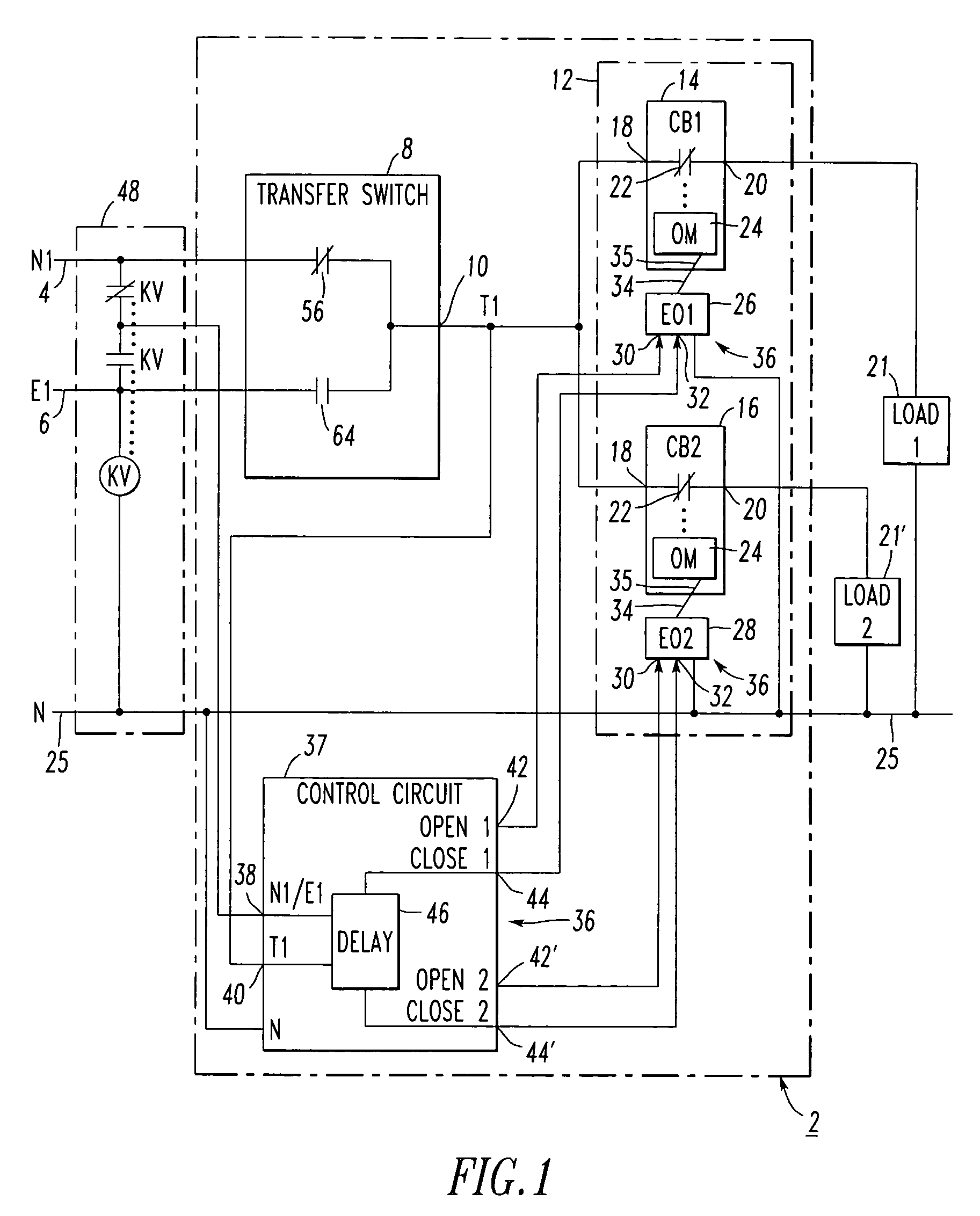
[0026]FIG. 2 shows a control circuit 50 for step loading a distribution panel (e.g., the distribution panel 12 of FIG. 1) using two example electrical operators 26,28 (EO1, EO2) and two example time delay timers 52,54 (EO TIMER 1, EO TIMER 2). Although two electrical operators 26,28 are shown, the invention is applicable to one, three or more of such electrical operators for one, three or more corresponding loads (e.g., the loads 21,21′ of FIG. 1).

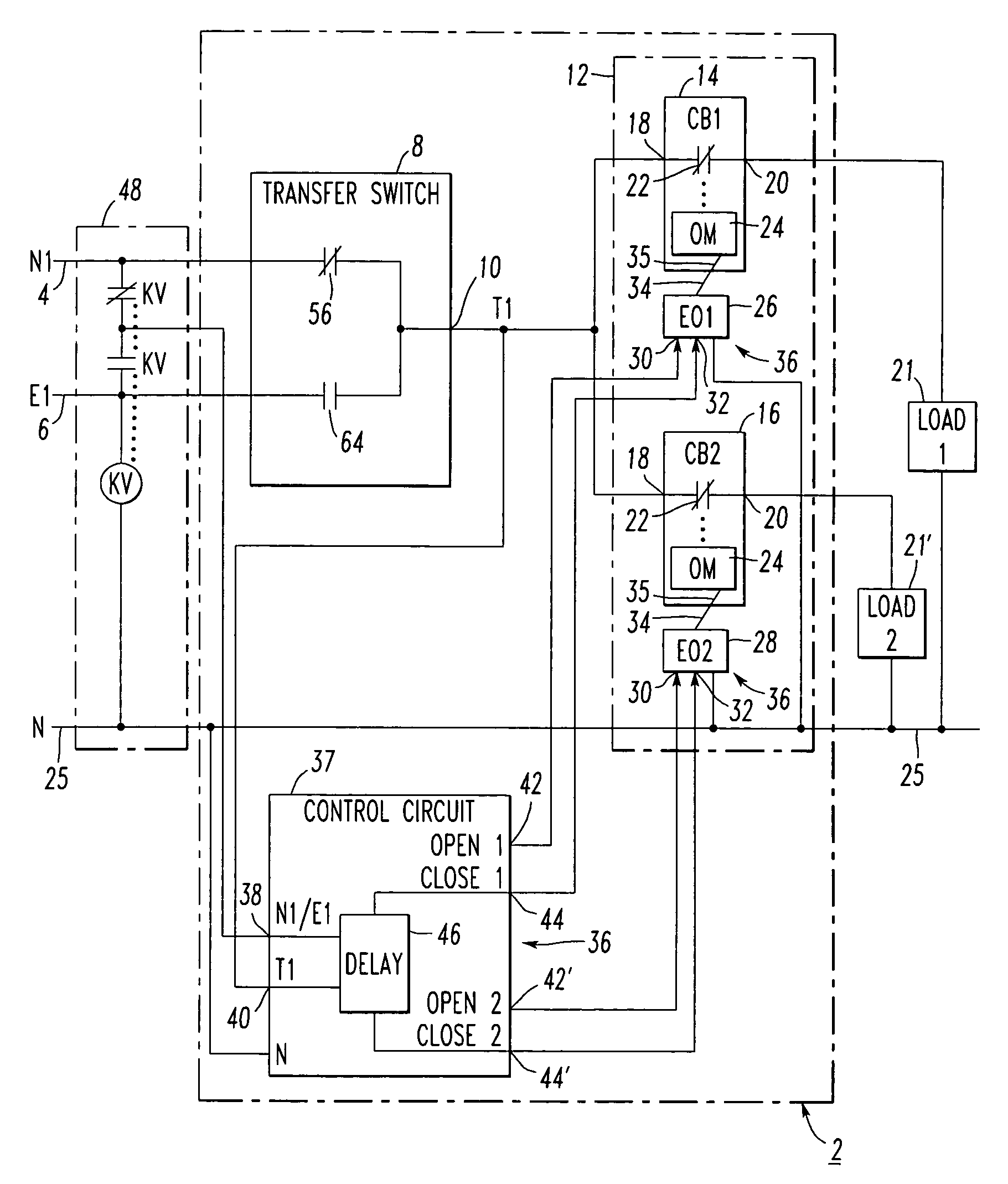
[0027]Initially, the first or normal power source N14 (FIG. 1) is available and is connected to the load output (T1) 10 of the transfer switch (e.g. transfer switch 8 of FIG. 1), which applies the power source N14 to the load output T110 through closure 56. A load sensing relay K158 is energized and power is supplied to the timers 52,54 and then to the electrical operators 26,28. Internal cutoff switches (not shown) sense when the switching operation (e.g., of CB114 and CB216 of FIG. 1) is complete and remove power from the EOs 26,28.

[0028...

example 2

[0032]FIG. 3 shows an example control circuit 80 employing a suitable controller 82 (e.g., a programmable logic controller (PLC); another suitable controller; a suitable control circuit including normally open and / or closed contacts). Initially, the first or normal power source N14 (FIG. 1) is available and is connected to the load output (T1) 10 of the transfer switch (e.g., transfer switch 8 of FIG. 1), which applies the power source N14 to the load output T110 through closure 56. The load sensing K1 relay coil 60 is energized, NO contact 66 is closed and power is supplied to the NC contacts 84,86 (KA, KB) and then to the close inputs 32 of the EOs 26,28 when those contacts are closed. For example, as shown in FIG. 4, contacts KA NC 84 and KB NC 86 may be closed immediately after the normal power source N14 (FIG. 1) reaches a suitable voltage as detected by the controller 82 at analog input (AI1) 88. For example, the EOs 26,28 may employ internal cutoff switches (not shown), which...

example 3

[0036]In this example, the KC NO contact 90 of FIG. 3 is replaced by a short circuit (not shown). Both modes of operation function in the same manner for the transition from N14 to E16, or from E16 to N14. For example, this occurs regardless whether the cause of transfer is a loss of a power source, an engine test function, a plant exercise function, a load shed from utility function, or another suitable cause. The step loading depends upon the transfer switch 8 (FIG. 1), since the transfer switch's time delay in its neutral position, which is greater than or equal to the time to open all of the controlled distribution circuit breakers 14,16 (FIG. 1), is employed in order to ensure that all EOs 26,28 open prior to connection to the power source E16.


PUM


Abstract

A control system for a power distribution system includes electrical operators each of which has an open input, a close input and an operator member adapted to cooperate with a corresponding circuit breaker operating mechanism. Each operator member responds to the corresponding open input to actuate the operating mechanism and open the corresponding circuit breaker, and responds to the corresponding close input to actuate the operating mechanism and close the corresponding circuit breaker. A control circuit includes an input for a normal power source, an input for an emergency power source, open outputs electrically connected to the open inputs of the corresponding electrical operators, and close outputs electrically connected to the close inputs of the corresponding electrical operator. The control circuit delays one or more of the close outputs or inhibits one or more of the close outputs after a transfer switch output switches to the emergency source.

Description

BACKGROUND OF THE INVENTION[0001]1. Field of the Invention[0002]The present invention relates to power distribution systems and, more particularly, to control circuits for distribution panels powered from transfer mechanisms, such as, for example, transfer switches. The invention also relates to control systems for power distribution systems.[0003]2. Background Information[0004]Alternate power sources are provided for any number of applications, which cannot withstand a lengthy interruption in electric power. Typically, power is provided from a primary source with back-up power provided by a secondary source. Often, the primary source is a utility and the secondary source is an auxiliary power source, such as an engine driven generator or a second utility source. The transfers between the two power sources can be made automatically or manually.[0005]In the case of a generator driven auxiliary power source, power must be stabilized before the transfer can be made to the secondary sou...

Claims


Application Information

Patent Timeline
Patent Type & Authority Patents(United States)
IPC IPC(8): H02J9/06H01H7/00H02J3/00H02J9/08
CPCH02J3/005H02J9/061H02J2009/068H02J9/068H02J3/007
Inventor LATHROP, TODD M.HANNA, JAMES R.
Owner EATON INTELLIGENT POWER LTD
Why Eureka
Try Eureka