Circular polarity elliptical horn antenna

a circular polarity, elliptical horn technology, applied in the field of antenna systems, can solve the problems of difficult to achieve good circular polarity cross polarization isolation, poor cross polarization performance, etc., and achieve good circular polarity performan

Active Publication Date: 2007-07-03
PRO BRAND INT
View PDF8 Cites 61 Cited by
  • Summary
  • Abstract
  • Description
  • Claims
  • Application Information

AI Technical Summary

Benefits of technology

[0010]The present invention meets the needs described above in antenna feed horns and associated antenna systems for receiving circular polarity beams. This type of antenna system, which may be implemented with a single horn or one or more multiple-horn antenna feed blocks, are designed to achieve good circular polarity performance over broad and multiple frequency bands.

Problems solved by technology

This is where the challenge arises.
It is difficult to achieve good circular polarity cross polarization isolation (also referred to as x-polarization or x-pol isolation) when using an elliptical beam feed with a circular polarity polarizer (also referred to as a CP polarizer) approaches.
The problem arises because an elliptical horn (or most any non-axially symmetric horn) introduces a differential phase shift between orthogonal electric fields that are parallel (or near parallel) to either the wide or narrow sides of the horn.
Simply attaching a conventional CP polarizer to a feed horn with an elliptical portion results in poor cross-polarization performance due to the differential phase and amplitude characteristics imparted by the elliptical portion of the feed horn.
When this occurs the result is a theoretically lossless conversion of the received power conversion from circular polarity to linear polarity (vertical polarity in this case).
So a polarizer designed to convert circular polarity to linear polarity will have poor CP cross polarization (cross polarization) performance as shown in FIG. 1D.
This approach is easy to implement but results in significant compromises (degradations) in efficiency, gain noise temperature, beam width, and side lobe performance of the reflector system, because the circular beam feeds do not properly illuminate the elliptical reflector.
This situation is shown in FIG. 2, in which the antenna horn illumination level along the short axis of the reflector is too high resulting in large amounts of wasted spillover energy that degrades gain, efficiency, and noise temperature.
In addition, the antenna horn illumination level along the long axis of the reflector is too low resulting in degraded taper efficiency and gain.
In addition, this improper illumination makes it very difficult to achieve desired beam width and side lobe performance.
In addition, for multi-beam applications where a single reflector is used to receive from multiple beam sources (typically satellites) that are closely spaced, use of a circular feed increases the physical spacing required between the feeds, which limits the closeness of the beams that the antenna can receive.
Regardless, this metal structure complicates the manufacturability of the horn making it more difficult to die cast or machine.

Method used


Image

  • Circular polarity elliptical horn antenna
  • Circular polarity elliptical horn antenna
  • Circular polarity elliptical horn antenna

Examples


embodiment 400

[0096]The antenna feed horn 600 described with reference to FIGS. 6A-B, is a broadband high performance elliptical beam circular polarity design that employs an elliptical beam horn deliberately designed to work in conjunction with an additional opposite slope phase differential section to greatly improve performance over very broad frequency bands as shown in FIG. 6C. To enable this embodiment, the inventor recognized that the phase differential introduced by most circular polarizers and the elliptical horn 400 (FIGS. 4A-B) are not a constant over the desired bandwidth. It is generally sloped versus frequency as shown in FIG. 7. So for the elliptical horn of embodiment 400, and for most circular polarity polarizers, the desired 90 degree total phase differential needed for complete CP conversion only occurs at a single frequency. This slope in phase differential versus frequency fundamentally limits the cross polarization performance over a wide bandwidth.

[0097]For this embodiment,...
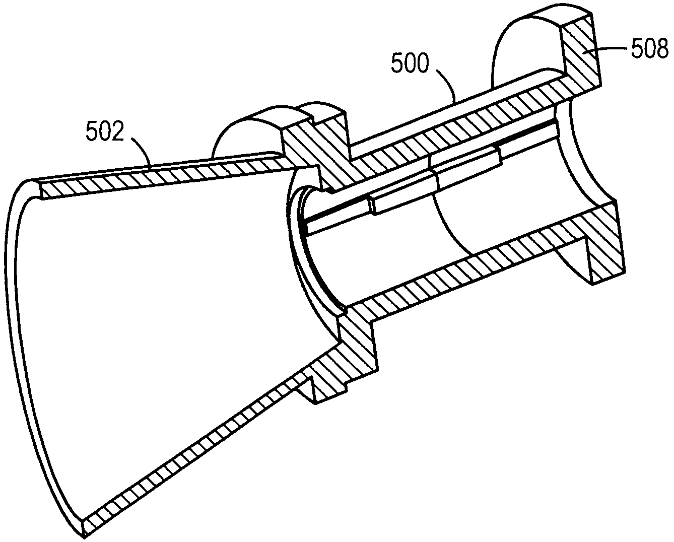
embodiment 500

[0103]The embodiment 500 shown FIGS. 5A-C is an elliptical beam circular polarity design that employs an elliptical beam horn with an additive phase differential section to achieve CP polarization conversion over modest bandwidths. For this embodiment, the inventor recognized that the phase differential “X” introduced between orthogonal linear components by the elliptical horn is often something other than 90 degrees (X=35 degrees for example) and that an additive phase differential section can be added to provide the additional phase differential Y (Y=55 degrees in this example) to obtain a total phase differential of 90 degrees or an odd integer multiple of 90 degrees ( . . . −630 degrees, −450 degrees, −270 degrees, −90 degrees, 90 degrees, 270 degrees, 450 degrees, 630 degrees . . . ) near center band. The nominal phase differentials from the horn transition section and the additive phase differential section are indeed additive or in the same direction (if one introduces a phas...

third embodiment

[0121]For antenna feed horn 1100, the total length of the horn, phase compensation section and conventional polarizer will in general be slightly longer and more difficult to make than the antenna feed horn 400 (FIGS. 4A-B) and significantly longer and moderately more difficult to make than the antenna feed horn 600 (FIGS. 6A-B). However the phase compensation section of this third embodiment could be easily and cost effectively integrated into the horn casting.

[0122]Referring now to FIGS. 10A-B and 12A-C, all of these embodiments can be used in single-feed or multi-feed reflector systems where the feeds are mounted separately or integrated in one or more housings that are mounted on an antenna dish to generate multiple receive and / or transmit beams for receiving from or transmitting to multiple nominal sources and / or receiver locations such as multiple satellite locations that can be separated by as little one degrees and as much as 180 degrees. FIGS. 3A-D illustrate a system that ...


PUM


Abstract

A relatively low cost, easy to install and aesthetically pleasing digital video broadcast from satellite (DVBS) elliptical horn antenna designed as part of a reflector antenna system to receive satellite television broadcast signals with circular polarity. This type antenna may be implemented with a single antenna feed horn with multiple feed horns that may be arranged separately or in one or more integral feed horn blocks. The antennas may be designed to achieve acceptable circular polarity performance over broad and multiple frequency bands through the use of oppositely sloped differential phase differential sections.

Description

REFERENCE TO RELATED APPLICATIONS[0001]This application claims priority to commonly-owned copending U.S. Provisional Patent Application Ser. No. 60 / 572,080 entitled “Small Wave-Guide Radiators For Closely Spaced Feeds on Multi-Beam Antennas” filed May 18, 2004, which is incorporated herein by reference; and U.S. Provisional Patent Application Ser. No. 60 / 571,988 entitled “Circular Polarization Technique for Elliptical Horn Antennas” filed May 18, 2004, which is also incorporated herein by reference.TECHNICAL FIELD[0002]The present invention is generally related to antenna systems designed to receive broadcast signals with circular polarity and, more particularly, is directed to digital video broadcast satellite (DVBS) antenna systems.BACKGROUND OF THE INVENTION[0003]An increasing number of applications, such as digital video satellite broadcast television systems, utilize elliptical antenna reflectors to improve gain and interference rejection in desired directions. This is particul...

Claims


Application Information

Patent Timeline
Patent Type & Authority Patents(United States)
IPC IPC(8): H01Q13/00H01Q13/02H01Q25/00
CPCH01Q13/0225H01Q25/007H01Q13/0258
Inventor COOK, SCOTT J.
Owner PRO BRAND INT
Why Eureka
Try Eureka