Method and apparatus for generating dispersed cluster screen

a cluster screen and cluster screen technology, applied in the field of rendering systems, can solve the problems of cluster screen structure, unstable printing mechanism of laser printer, and large remaining void size of printing device such as laser printer, so as to reduce the size of the largest remaining void

Inactive Publication Date: 2007-07-03
SEIKO EPSON CORP
View PDF18 Cites 7 Cited by
  • Summary
  • Abstract
  • Description
  • Claims
  • Application Information

AI Technical Summary

Benefits of technology

[0011]In another embodiment, a method for generating a dispersed cluster screen defining a stable environment for printing an image is provided. The method initiates with generating a pattern of cluster centroids. Then a cluster growth sequence is defined. Next, a cluster is grown around each cluster centroid according to the cluster growth sequence. A largest remaining void is identified, and a dot is placed alongside an existing cluster proximate to the largest remaining void in a manner to reduce a size of the largest remaining void.
[0012]In yet another embodiment, a computer readable medium having program instructions for generating a dispersed cluster screen is provided. The computer readable medium includes program instructions for generating a cluster centroid. Program instructions for defining a cluster growth sequence are also provided. Program instructions for growing a cluster around each cluster centroid according to the cluster growth sequence are included. Program instructions for identifying a largest remaining void, and for placing a dot alongside an existing cluster proximate to the largest remaining void in a manner to reduce a size of the largest remaining void are also provided.

Problems solved by technology

The printing mechanism for a laser printer tends to be unstable when printing a single dot.
As can be seen in block 104, isolated single dots occur, thereby causing instability in printing device such as a laser printer.
However, the structures of clustered dot screens tend to be visible due to the periodicity.
Thus, the laser printing mechanism becomes unstable for the light and mid tone regions and does not satisfactorily reproduce the small halftone dots associated with the stochastic screening model.

Method used


Image

  • Method and apparatus for generating dispersed cluster screen
  • Method and apparatus for generating dispersed cluster screen
  • Method and apparatus for generating dispersed cluster screen

Examples


Embodiment Construction

[0026]An invention is described for an apparatus and method for providing a stable output while minimizing moiré patterns and visible structures when printing images from a printing device. It will be obvious, however, to one skilled in the art, that the present invention may be practiced without some or all of these specific details. In other instances, well known process operations have not been described in detail in order not to unnecessarily obscure the present invention. FIGS. 1A-1C are described in the “Background of the Invention” section. The term about as used herein refers to + / − 10% of the referenced value.

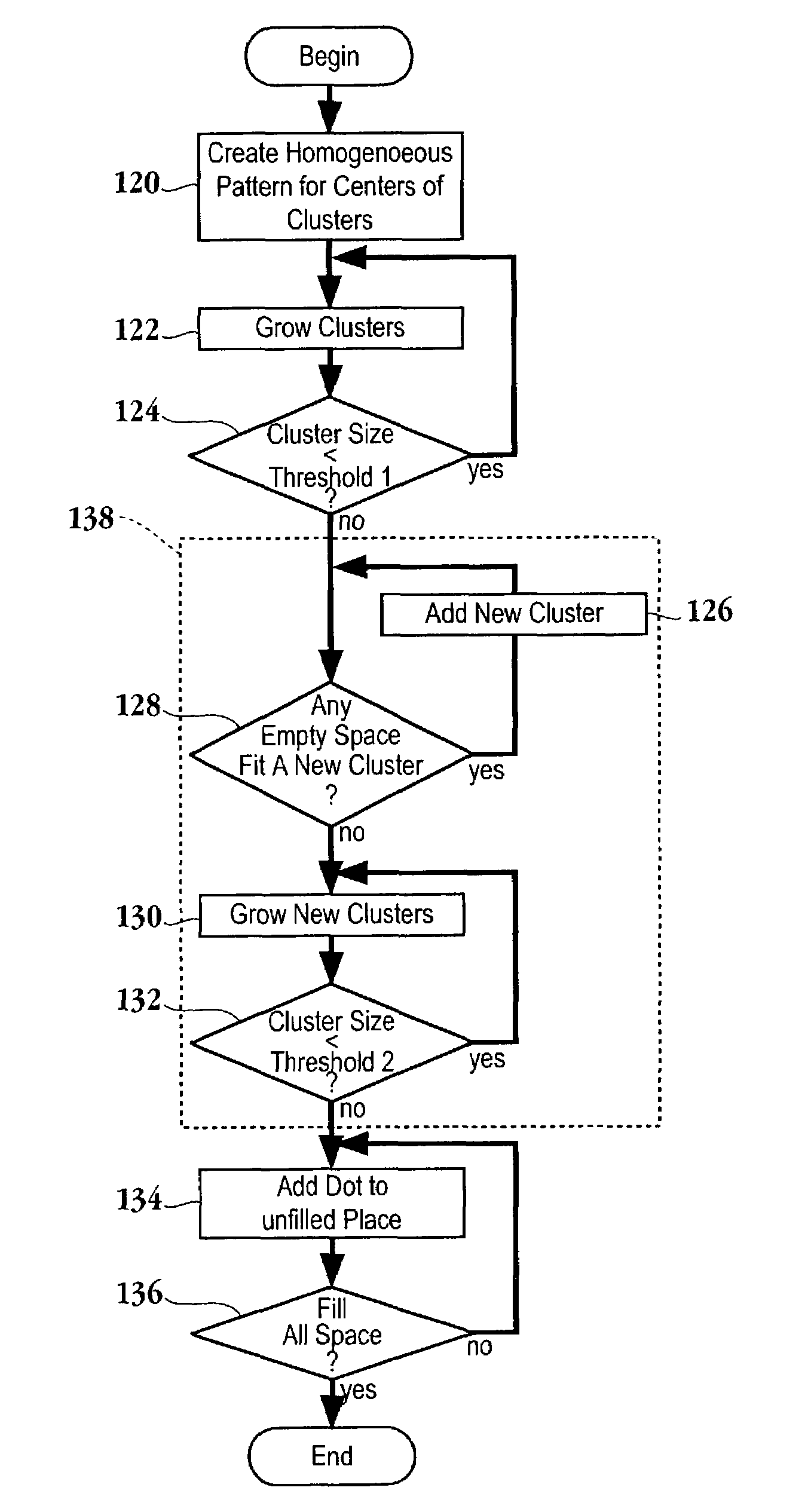
[0027]The embodiments of the present invention provide an apparatus and method for generating a dispersed cluster screen to be used when printing a digital image. The image data is translated into a plurality of dots, also referred to as centroids, that are distributed in a homogenous fashion. Thus, the visible structure patterns prevalent with cluster dot screens is m...


PUM


Abstract

A method for generating a dispersed cluster screen defining a stable environment for printing an image is provided. The method initiates with generating a pattern of cluster centroids. Then a cluster growth sequence is defined. Next, a cluster is grown around the cluster centroid according to the cluster growth sequence. A computer readable medium having program instructions for generating a dispersed cluster screen and an image forming device configured to print an image according to a dispersed cluster screen technique are also provided.

Description

BACKGROUND OF THE INVENTION[0001]1. Field of the Invention[0002]This invention relates generally to rendering systems and more particularly to a method and apparatus for generating a dispersed cluster screen that produces stable light-tones and minimizes visual repeated patterns.[0003]2. Description of the Related Art[0004]Printers are now a commonplace item in the home as well as the office environment. Through the process of halftoning, a bi-level device, e.g., a laser printer, transforms an image with greater amplitude resolution to an image with lesser amplitude resolution. The basic premise is to trade off resolution for greater apparent tone depth. Digital halftoning techniques may be classified as frequency modulation (FM) screening or amplitude modulation (AM) screening. FM screening, also known as stochastic screening, uses algorithms that place dots in neither completely regular nor completely random fashion. One of the biggest advantages of FM screening is that it elimina...

Claims


Application Information

Patent Timeline
Patent Type & Authority Patents(United States)
IPC IPC(8): H04N1/405H04N1/407H04N1/409B41J2/52G06T5/00
CPCH04N1/4055
Inventor HUANG, JINCHENGBHATTACHARJYA, ANOOP K.
Owner SEIKO EPSON CORP
Why Eureka
Try Eureka