Distance protective relay using a programmable thermal model for thermal protection

Active Publication Date: 2007-07-03
SCHWEITZER ENGINEERING LABORATORIES
View PDF3 Cites 4 Cited by
  • Summary
  • Abstract
  • Description
  • Claims
  • Application Information

AI Technical Summary

Problems solved by technology

This can lead to inaccurate results in some cases.

Method used


Image

  • Distance protective relay using a programmable thermal model for thermal protection
  • Distance protective relay using a programmable thermal model for thermal protection
  • Distance protective relay using a programmable thermal model for thermal protection

Examples


Embodiment Construction

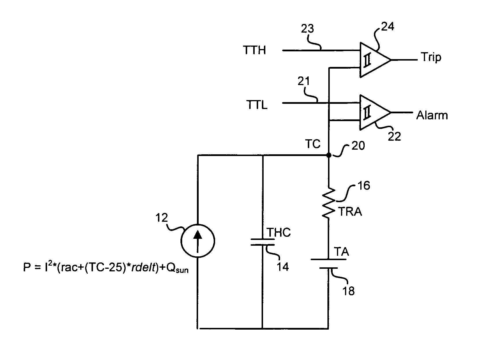
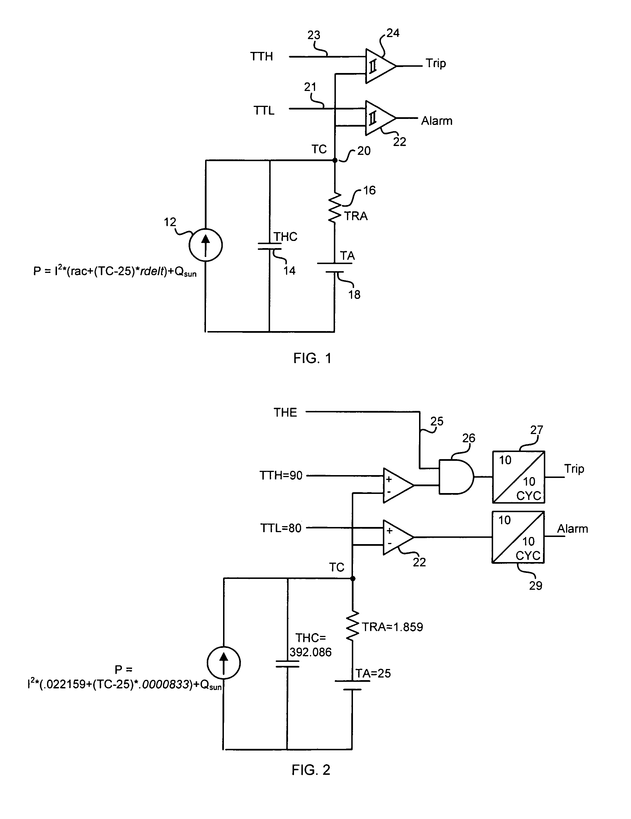
[0010]As indicated above, use is made of first order thermal models to determine the temperature of electrical conductors, such as for instance the temperature in various parts of an induction motor. These principles are set out in a paper by S. E. Zocholl and Gabriel Benmouyal entitled “Using Thermal Limit Curves to Define Thermal Models for Induction Motors”, Proceedings of the 28th Annual Western Protective Relay Conference, Spokane, Wash., October 2001. The first order thermal model for protection of a power line is expressed as first order differential equation:

[0011]Power⁢⁢Supplied⁢⁢(P)⁢-⁢Losses=ⅆ(TC)ⅆt(1)

The equations below use the following variables:[0012]P=heat power input to the conductor (kW / kft)[0013]THC=conductor heat capacity (kJ / ° C. kft)[0014]TRA=thermal resistance to ambient (° C. kft / kW)[0015]TC=estimated conductor temperature (° C.)[0016]TA=ambient temperature (° C.)[0017]TI=conductor initial temperature (° C.)[0018]I=conductor current (A RMS)[0019]rac=AC conduct...


PUM


Abstract

The system includes a distance protective relay for power lines which includes a logic capability which is responsive to settings entered into the relay by an end user to implement the value of those settings into stored thermal model equations which emulate the temperature of the power line conductor. The logic within the relay is organized and has the capability of receiving the setting values entered by the user and to use those in the logic equations to determine the temperature of the conductor.

Description

TECHNICAL FIELD[0001]This invention relates generally to power line thermal protection, and more specifically concerns such thermal protection implemented with a first order thermal model emulating the temperature of the power line.BACKGROUND OF THE INVENTION[0002]Thermal protection for power lines is accomplished by monitoring the temperature of the wire conductor and generating a trip signal which opens a circuit breaker when the conductor temperature becomes greater than the maximum allowed temperature for the conductor. The temperature of the conductor is not measured directly, but is obtained by using a first order thermal model for the conductor. This involves using a heat balance equation (heat input minus heat losses) of a 1000 foot section of conductor.[0003]The 1000 foot section of the line is assumed to have the highest temperature and to be exposed to the maximum solar radiation. The heat input portion in the equation is mainly due to heat dissipated in the conductor res...

Claims


Application Information

Patent Timeline
Patent Type & Authority Patents(United States)
IPC IPC(8): H02H5/04H02H3/00H02H6/00H02H7/22
CPCH02H6/005H02H3/006H02H7/226
Inventor SCHWEITZER, III, EDMUND O.BENMOUYAL, GABRIELBRYSON, MICHAEL B.
Owner SCHWEITZER ENGINEERING LABORATORIES
Why Eureka
Try Eureka