Electronic device with uniform heat-dissipation

a technology of electric devices and heat dissipation efficiency, applied in the direction of electrical equipment, cooling/ventilation/heating modifications, and modifications by conduction heat transfer, etc., can solve the problems of low heat dissipation efficiency of products, increase of the temperature of the whole adapter, and partial electric power consumption, so as to achieve uniform heat dissipation, poor heat dissipation efficiency, and high thermal resistan

Active Publication Date: 2007-07-03
DELTA ELECTRONICS INC
View PDF12 Cites 21 Cited by
  • Summary
  • Abstract
  • Description
  • Claims
  • Application Information

AI Technical Summary

Benefits of technology

[0008]An object of the present invention is to provide an electronic device with uniform heat-dissipation, which comprises the matching structures of the metal shielding and the housing, so as to overcome the defects of poor heat-dissipation efficiency and nonuniform temperature distribution of the conventional electronic device due to the high thermal resistance in the space formed between the inner side of the housing and the side of the printed circuit board assembly.
[0009]According to an aspect of the present invention, there is provided an electronic device with uniform heat-dissipation. The electronic device comprises a housing, a circuit board, and a metal shielding. The housing has concavities at inner sides thereof, and the circuit board is disposed within the housing. The metal shielding is disposed between the housing and the circuit board and has protrusions at outer sides thereof to match up the concavities of the housing. Thereby, the metal shielding substantially stays close to the housing for allowing the electronic device to dissipate heat uniformly.

Problems solved by technology

When the adapter is under operation, partial electric power will be consumed.
As the watt consumption increases, more and more heat is generated, resulting in the increase of the temperature of the whole adapter.
The nonuniform temperature distribution of the adapter 1 will cause the large temperature difference on side surface and top surface, so the heat-dissipation efficiency of product is very low.
Moreover, it will cause the over-temperature of the high-temperatured heat flow area.
When the high-temperatured heat flow area is close to the important electronic components on the printed circuit board, the adapter 1 will be broken easily or its lifespan will be shortened due to the over-temperature condition, and even more, a fire accident may occur.

Method used


Image

  • Electronic device with uniform heat-dissipation
  • Electronic device with uniform heat-dissipation
  • Electronic device with uniform heat-dissipation

Examples


Embodiment Construction

[0027]The present invention will now be described more specifically with reference to the following embodiments. It is to be noted that the following descriptions of preferred embodiments of this invention are presented herein for purpose of illustration and description only; it is not intended to be exhaustive or to be limited to the precise form disclosed.

[0028]The present invention relates to an electronic device with uniform heat-dissipation. The present techniques are illustrated with the following embodiments for an adapter, but the electronic device that is applicable to the present techniques is not limited to the adapter. Any electronic device, such as a power supply or a charger, which is applicable to the following techniques, is incorporated herein for reference.

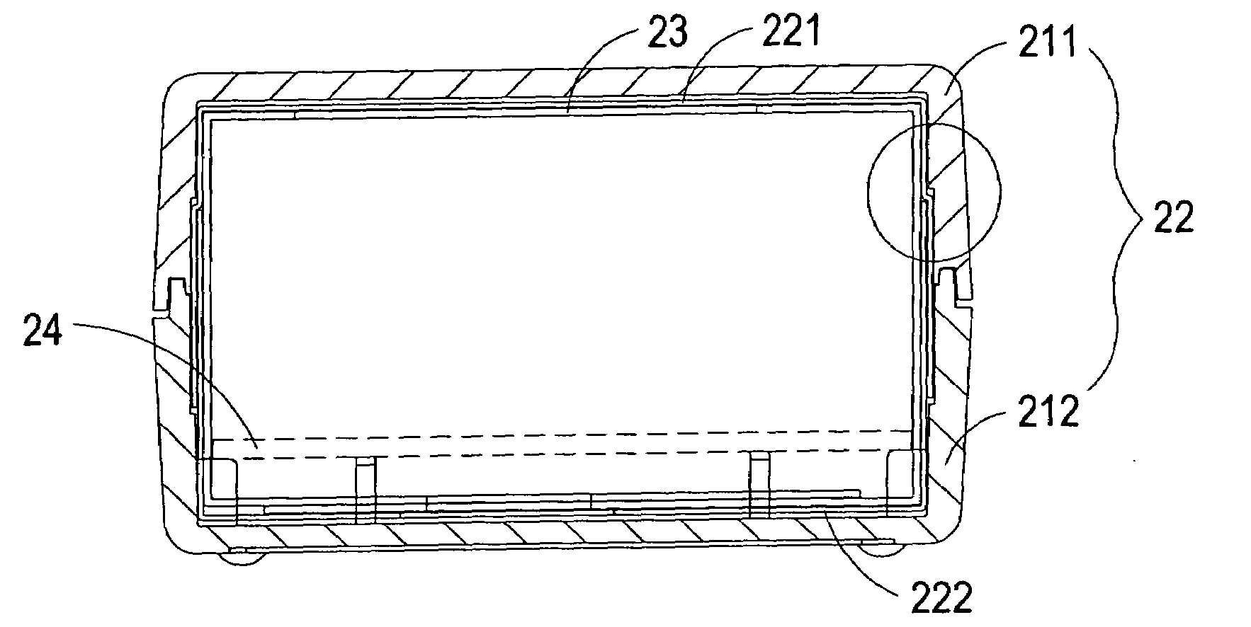
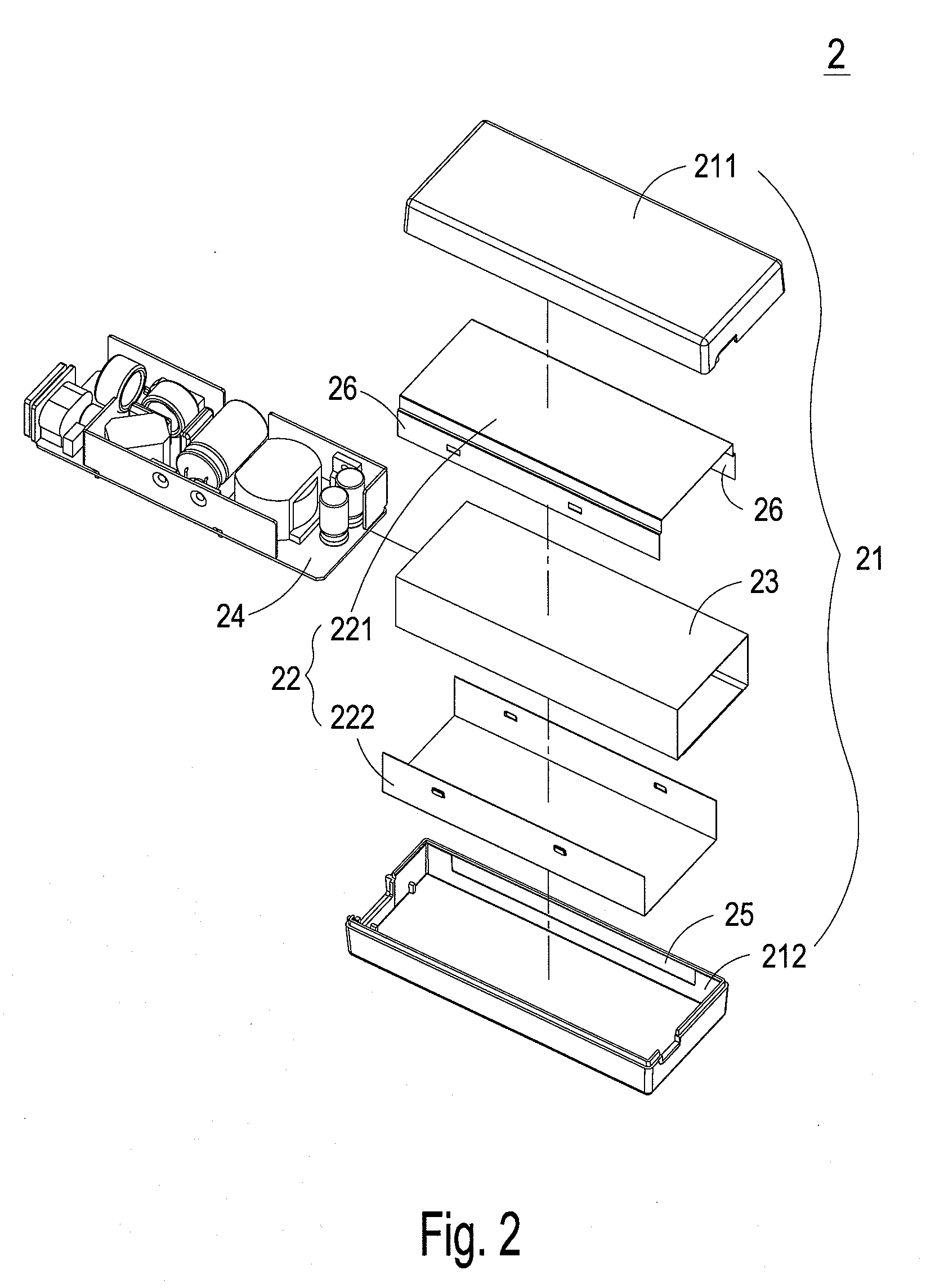
[0029]Please refer to FIG. 2, which is an exploded view showing the electronic device with uniform heat-dissipation according to the preferred embodiment of the present invention. As shown in FIG. 2, the electron...


PUM


Abstract

An electronic device with uniform heat-dissipation is disclosed. The electronic device comprises a housing, a circuit board, and a metal shielding. The housing has concavities at inner sides thereof, and the circuit board is disposed within the housing. The metal shielding is disposed between the housing and the circuit board and has protrusions at outer sides thereof to match up the concavities of the housing. Thereby, the metal shielding substantially stays close to the housing for allowing the electronic device to dissipate heat uniformly.

Description

FIELD OF THE INVENTION[0001]The present invention relates to an electronic device, and more particularly to an electronic device with uniform heat-dissipation.BACKGROUND OF THE INVENTION[0002]The portable electronic products or other electronic information products, such as the personal notebook or personal digital assistant, become indispensable electronic products in daily life. Since these electronic products are carried with the user usually, the adapter, power supply and charger are necessary accessories to keep enough power of the electronic products.[0003]Take the adapter as an example. When the adapter is under operation, partial electric power will be consumed. With the technical progress of the electronic product and in response to the requirement of the user, more and more electronic components are loaded on the printed circuit board in the interior of the electronic product, which increases the integration of the electronic components. Therefore, the electric power consu...

Claims


Application Information

Patent Timeline
Patent Type & Authority Patents(United States)
IPC IPC(8): H05K7/20H05K9/00
CPCH05K7/20509H05K9/005H05K7/20445
Inventor GUO, QINGLIN, DONGLI, BAO HUAZHANG, JIN FA
Owner DELTA ELECTRONICS INC
Why Eureka
Try Eureka