
Asynchronous system-on-a-chip interconnect

a technology of asynchronous system and chip, applied in the direction of phase-modulated carrier system, generating/distributing signals, instruments, etc., can solve the problems of difficult implementation of efficient interconnect solution, difficult to achieve synchronization, and no longer apply synchronization solution, etc., to achieve the effect of insensitive to variations in system module performan

Inactive Publication Date: 2007-07-03
INTEL CORP
View PDF27 Cites 59 Cited by
  • Summary
  • Abstract
  • Description
  • Claims
  • Application Information

AI Technical Summary

Benefits of technology

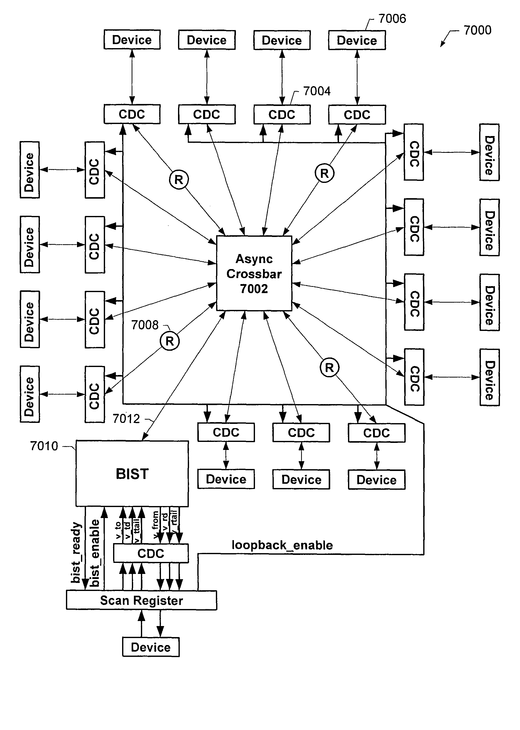
The present invention provides a system interconnect solution that can connect different system modules with different clock domains without being affected by the performance of the modules. The solution includes synchronous modules with different data rates and clock domain converters that convert data between the modules' clock domains and an asynchronous domain. An asynchronous crossbar is used to create a FIFO channel between the clock domain converters, allowing communication between the modules. The invention can be used in various system types such as multi-processor data processing systems and SONET interconnect switches.

Problems solved by technology

This makes it very difficult to implement an efficient interconnect solution.
Not only is this synchronization difficult to achieve, as soon as the performance of any of the modules (which are typically associated with different vendors) changes, i.e., clock speed increases, the ratios of the synchronization solution no longer apply, and a completely new solution must be implemented.

Method used


Image

  • Asynchronous system-on-a-chip interconnect
  • Asynchronous system-on-a-chip interconnect
  • Asynchronous system-on-a-chip interconnect

Examples


Embodiment Construction

[0049]Reference will now be made in detail to specific embodiments of the invention including the best modes contemplated by the inventors for carrying out the invention. Examples of these specific embodiments are illustrated in the accompanying drawings. While the invention is described in conjunction with these specific embodiments, it will be understood that it is not intended to limit the invention to the described embodiments. On the contrary, it is intended to cover alternatives, modifications, and equivalents as may be included within the spirit and scope of the invention as defined by the appended claims. In the following description, numerous specific details are set forth in order to provide a thorough understanding of the present invention. The present invention may be practiced without some or all of these specific details. In addition, well known process operations have not been described in detail in order not to unnecessarily obscure the present invention.

[0050]Asynch...


PUM


Abstract

Methods and apparatus are described relating to a system-on-a-chip which includes a plurality of synchronous modules, each synchronous module having an associated clock domain characterized by a data rate, the data rates comprising a plurality of different data rates. The system-on-a-chip also includes a plurality of clock domain converters. Each clock domain converter is coupled to a corresponding one of the synchronous modules, and is operable to convert data between the clock domain of the corresponding synchronous module and an asynchronous domain characterized by transmission of data according to an asynchronous handshake protocol. An asynchronous crossbar is coupled to the plurality of clock domain converters, and is operable in the asynchronous domain to implement a first-in-first-out (FIFO) channel between any two of the clock domain converters, thereby facilitating communication between any two of the synchronous modules.

Description

RELATED APPLICATION DATA[0001]The present application claims priority from U.S. Provisional Patent Application No. 60 / 444,820 for ASYNCHRONOUS INTERCONNECT SYSTEM filed on Feb. 3, 2003, the entire disclosure of which is incorporated herein by reference. The present application also claims priority from U.S. patent application Ser. No. 10 / 136,025 for ASYNCHRONOUS CROSSBAR CIRCUIT WITH DETERMINISTIC OR ARBITRATED CONTROL filed on Apr. 30, 2002, and U.S. patent application Ser. No. 10 / 212,574 for TECHNIQUES FOR FACILITATING CONVERSION BETWEEN ASYNCHRONOUS AND SYNCHRONOUS DOMAINS filed on Aug. 1, 2002, the entire disclosures of both of which are incorporated herein by reference for all purposes.BACKGROUND OF THE INVENTION[0002]The present invention relates to asynchronous digital circuit design and in particular to asynchronous circuitry for interconnecting a variety of system resources in the context of a system-on-a-chip.[0003]A so called “system-on-a-chip” (SOC) is typically designed...

Claims


Application Information

Patent Timeline
Patent Type & Authority Patents(United States)
IPC IPC(8): H04L27/04G06F1/12G06F13/42H01LH04J3/06H04L7/02H04L27/20H10N39/00
CPCG06F1/12G06F13/423H04L7/005H04Q3/0004G06F2213/0038H04L7/02H04L49/101H04L2012/5674H04Q2213/13034H04Q2213/13214H04Q2213/13322H04Q2213/13361H04Q2213/13362
Inventor CUMMINGS, URILINES, ANDREW
Owner INTEL CORP
Learn More