Optimizing the protection of wireless local area networks with real-time, flexible, perimeter sensor feedback

a wireless local area network and wireless local area technology, applied in the field of data communication protection, can solve the problems of signal strength decay, wlan radiation zones have a tendency to spill over or “bleed, extremely dangerous” and achieve the effect of preventing signal bleed

Inactive Publication Date: 2007-07-03
PEIKARI CYRUS
View PDF4 Cites 16 Cited by
  • Summary
  • Abstract
  • Description
  • Claims
  • Application Information

AI Technical Summary

Benefits of technology

[0011]In a first embodiment, the present invention provides a method and apparatus for protecting wireless networks by using radio frequency (RF) radiation sensors (sensors) on the physical perimeter of a campus to detect signal bleed outside of an acceptable geographic range. These sensors provide feedback to the central controller to flexibly adjust signal strength in real time, thus preventing signal bleed beyond an acceptable geographic range.

Problems solved by technology

However, the signal strength decays as users move towards the periphery of the sphere.
Unfortunately, WLAN radiation zones have a tendency to spill over or “bleed” radio frequency broadcasts beyond the defined, allowable perimeter of campus properties.
This is extremely dangerous, because unauthorized users can walk or drive by (while remaining safely outside of the property) and can intercept private data transmissions from the campus WLAN.
Unfortunately, the prior art suffers from several drawbacks.
In addition, environmental conditions affect signal bleed.
For example, weather changes will cause the signal bleed to wax and wane with time.
Currently, the prior art has no provision for automatically and flexibly adjusting perimeter RF signal bleed or directional signal strength in real time.
Thus, power consumption is not optimized, and interference between devices can occur.
In addition, uncontrolled, excessive signal bleed that changes over time and can subject the WLAN to interception and attacks from outside, malicious wardrivers.

Method used


Image

  • Optimizing the protection of wireless local area networks with real-time, flexible, perimeter sensor feedback
  • Optimizing the protection of wireless local area networks with real-time, flexible, perimeter sensor feedback
  • Optimizing the protection of wireless local area networks with real-time, flexible, perimeter sensor feedback

Examples


Embodiment Construction

[0019]The operation of the present invention will now be described in conjunction with the Drawing Figures.

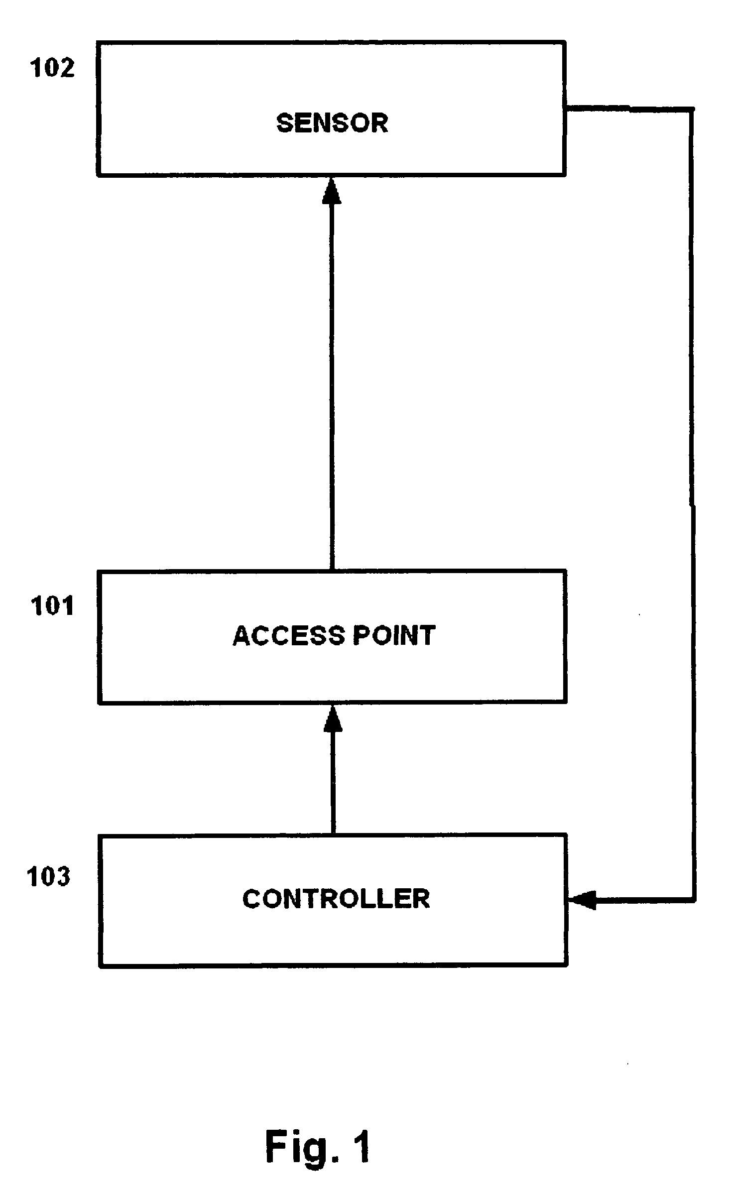
[0020]FIG. 1 is a flow diagram illustrating an embodiment of the present invention, which protects wireless networks by using radio frequency (RF) radiation sensors (sensors) on the physical perimeter of a campus to detect signal bleed outside of an acceptable geographic range. These sensors provide feedback to the central controller to flexibly adjust signal strength in real time, thus preventing signal bleed beyond an acceptable geographic range.

[0021]As shown in FIG. 1, the access point (AP) at step 101 produces a radio frequency signal. This signal is broadcast across the campus, and may be received by the exemplary sensor located on the perimeter at step 102.

[0022]If the perimeter sensor at step 102 detects a predetermined signal strength from the AP at step 101, this means that the signal is bleeding beyond the desired range. The perimeter sensor at step 102 will then aut...


PUM


Abstract

The invention optimizes the security of data communication on wireless local area networks (WLANs). This invention uses radio frequency (RF) radiation sensors (sensors) on the physical perimeter of a campus, or between nodes in a wireless mesh network, to detect signal bleed outside of an acceptable geographic range. In a preferred embodiment, this is achieved by (1) setting the acceptable signal strength (“bleed”) to be allowed at the perimeter, (2) sensing the RF signal strength at the perimeter sensors, (3) providing feedback from the sensors to the central radiation source controller (controller), (4) adjusting the central radiation source signal strength upwards or downwards based on acceptable ranges, (5) repeating this procedure in real time to provide constant optimization.

Description

CROSS-REFERENCE TO RELATED APPLICATIONS[0001]Not ApplicableSTATEMENT REGARDING FEDERALLY SPONSORED RESEARCH OR DEVELOPMENT[0002]Not ApplicableFIELD OF THE INVENTION[0003]The invention relates to the protection of data communication. In particular, the invention is directed to increasing the security of wireless networks.BACKGROUND OF THE INVENTION[0004]Wireless networks and wireless local area networks (WLANs) are becoming increasingly common and are forming an increasingly vital part of global networks. The typical WLAN has one or more access points (APs) that broadcast and receive wireless signals from the wireless network. On a typical corporate campus, the intent is to provide wireless coverage for the central buildings of the campus while minimizing signal drift (i.e., “bleed”) outside of the geographic boundaries of the campus property.[0005]A typical access point generates a radio frequency signal in a spherical distribution. Users near the center of the sphere (i.e., closest...

Claims


Application Information

Patent Timeline
Patent Type & Authority Patents(United States)
IPC IPC(8): H04B1/00H04B7/00H04B7/005H04W16/14H04W16/20H04W52/02H04W52/30
CPCH04W16/14H04W52/30H04W16/20
Inventor PEIKARI, CYRUS
Owner PEIKARI CYRUS
Why Eureka
Try Eureka