Miniature cutting insert holder

a technology for insert holders and miniature cutting, which is applied in the field of miniature cutting insert holders, can solve the problems of impracticality of screw and serration configuration, and achieve the effect of easy detachment and low cos

Active Publication Date: 2007-07-10
VERSABAR TOOLS LLC
View PDF26 Cites 30 Cited by
  • Summary
  • Abstract
  • Description
  • Claims
  • Application Information

AI Technical Summary

Benefits of technology

[0003]In accordance with one embodiment of the invention, a cutting insert holder is provided, of the type that has a head with a pocket that holds the cutting insert, wherein the head is easily detachable from a bar device in a construction that is of low cost and that allows the holder to fit into a small workpiece hole. The head has a front part that holds the cutting insert and that is of small height, and has a rear part that is of a greater height about equal to that of the bar device. A screw extends through a hole in the head rear part and through a threaded hole in the front of the bar device, to hold the head securely on the bar device. A recess and projection are provided, one on the rear of the head and the other on the front of the bar device, to precisely locate the head on the bar device. The screw extends within the recess and projection, so widely-spaced locating surfaces are provided on the recess and projection.

Problems solved by technology

For bar diameters of under ⅝th inch the cost to manufacture a screw and serration configuration makes such system impractical.

Method used


Image

  • Miniature cutting insert holder
  • Miniature cutting insert holder
  • Miniature cutting insert holder

Examples


Embodiment Construction

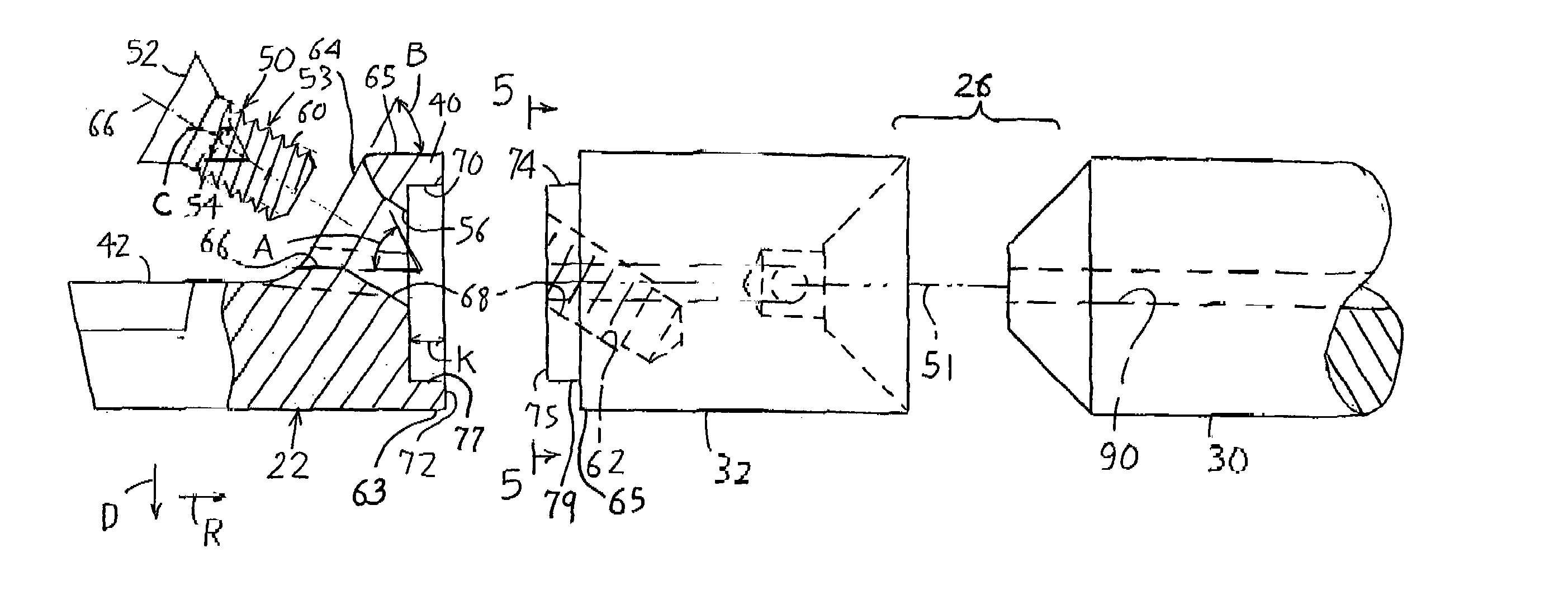
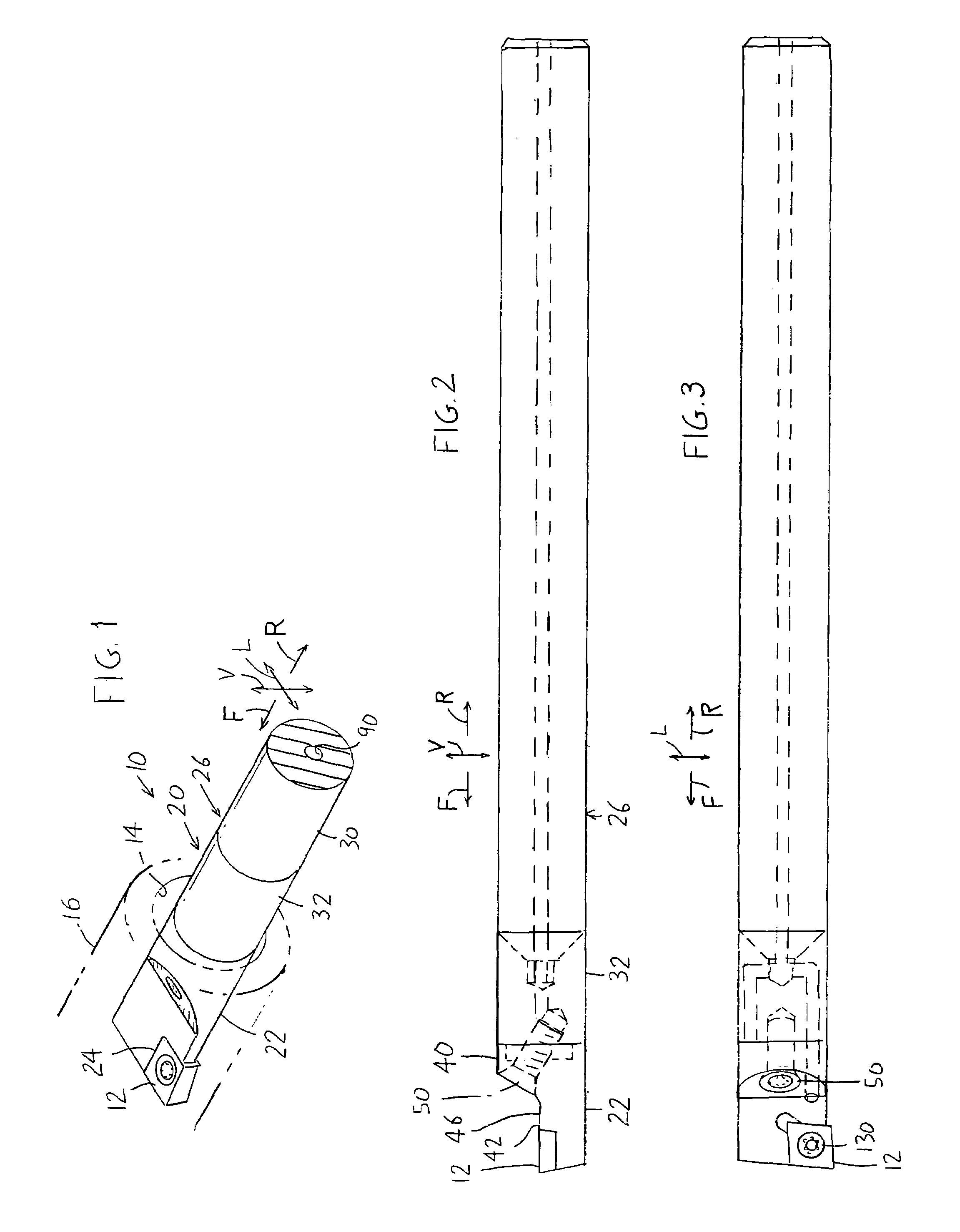
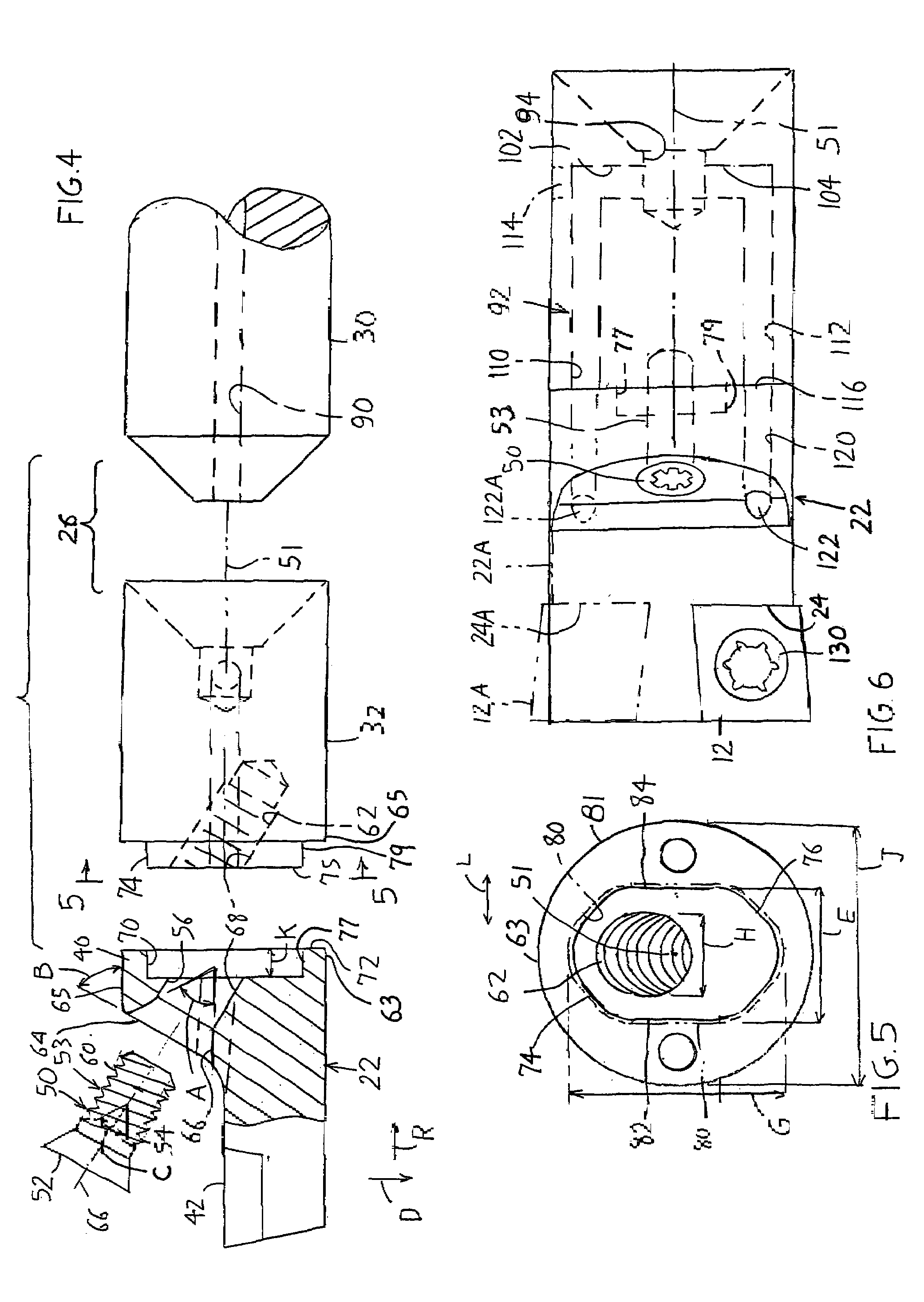
[0013]FIG. 1 shows a cutting apparatus 10 of the present invention, which includes a cutting insert 12 that has been advanced forwardly F so it lies in a hole 14 of a workpiece 16. The workpiece is mounted on a lathe spindle that turns the workpiece. The insert is held by a holder 20 that includes a head 22 with a pocket 24 that receives the cutting insert. The holder also includes a bar device 26 formed by a shank or bar 30 and a mount 32 that forms a front part of the bar device and that is fixed to the front end of the bar. The head 22 is detachably mounted on the mount 32. In the prior art, the smallest practical cutting apparatus with detachable head could fit only into a hole of ⅝th inch or greater diameter. A smaller cutting apparatus could be made by fixing the head to the bar device by brazing, but then the head is not detachable from the bar device.

[0014]FIG. 2 shows that the head 22 has a rear part 40 with a height in a vertical direction V that is about the same as the h...


PUM

PropertyMeasurementUnit
diameteraaaaaaaaaa
incline angleaaaaaaaaaa
angleaaaaaaaaaa

Abstract

A holder (20) for a cutting insert (12), which includes a head (22) with a pocket (24) for holding the cutting insert and a bar device (26) for supporting the head, allows the use of a removable head for a miniature head and bar device that fits into a small hole in a workpiece, and allows rapid and easy replacement of the head. The head has a front part (42) of small height for holding the cutting insert and has a taller rear part (40) of the same height as the bar device. The head rear part has a screw-receiving hole (56) that extends at a downward-rearward incline (A) into a corresponding threaded hole (62) at the front of the bar device. The head and bar device respectively have a recess (70) and a projection (74) that lie around the screw-receiving holes and that align the head and bar device. A coolant passageway system (92) in the bar device provides coolant for both right and left hand heads.

Description

BACKGROUND OF THE INVENTION[0001]Small holes drilled into a workpiece can be machined to form a precision finished surface on the hole walls, by rotating the workpiece on a lathe while a cutting insert is advanced within the hole. The cutting insert is mounted in a pocket of a holder head. It is often desirable to detachably mount the holder head on a holder bar device so the head can be replaced. In prior systems, holder heads on bar devices of ⅝th inch and larger diameters are held by a multiple screw / multiple serration system. In that system, precision mounting of the head on the bar device is achieved by miniature screws and multiple serrations on each part that interfit. For bar diameters of under ⅝th inch the cost to manufacture a screw and serration configuration makes such system impractical. In prior art systems for bar diameters under ⅝th inch the holder device is simply brazed to the bar device in a one piece construction.[0002]It would be desirable if a machining apparat...

Claims


Application Information

Patent Timeline
Patent Type & Authority Patents(United States)
IPC IPC(8): B23B29/02
CPCB23B27/10B23B27/1614B23B29/043B23B29/046B23B31/11B23B2231/0204Y10T407/14B23B2270/20Y10T82/2585Y10T407/227Y10T407/2272Y10T82/10B23B2231/24
Inventor LITTLE, ROGER
Owner VERSABAR TOOLS LLC
Why Eureka
Try Eureka