Fuel injection control device
a control device and fuel injection technology, applied in the direction of fuel injection apparatus, fuel feed system, engine components, etc., can solve the problems of system as a whole becoming costly, and achieve the effect of suppressing the fuel pressure loss
- Summary
- Abstract
- Description
- Claims
- Application Information
AI Technical Summary
Benefits of technology
Problems solved by technology
Method used
Image


Examples
first embodiment
[0029]the present invention will now be explained with reference to the drawings.
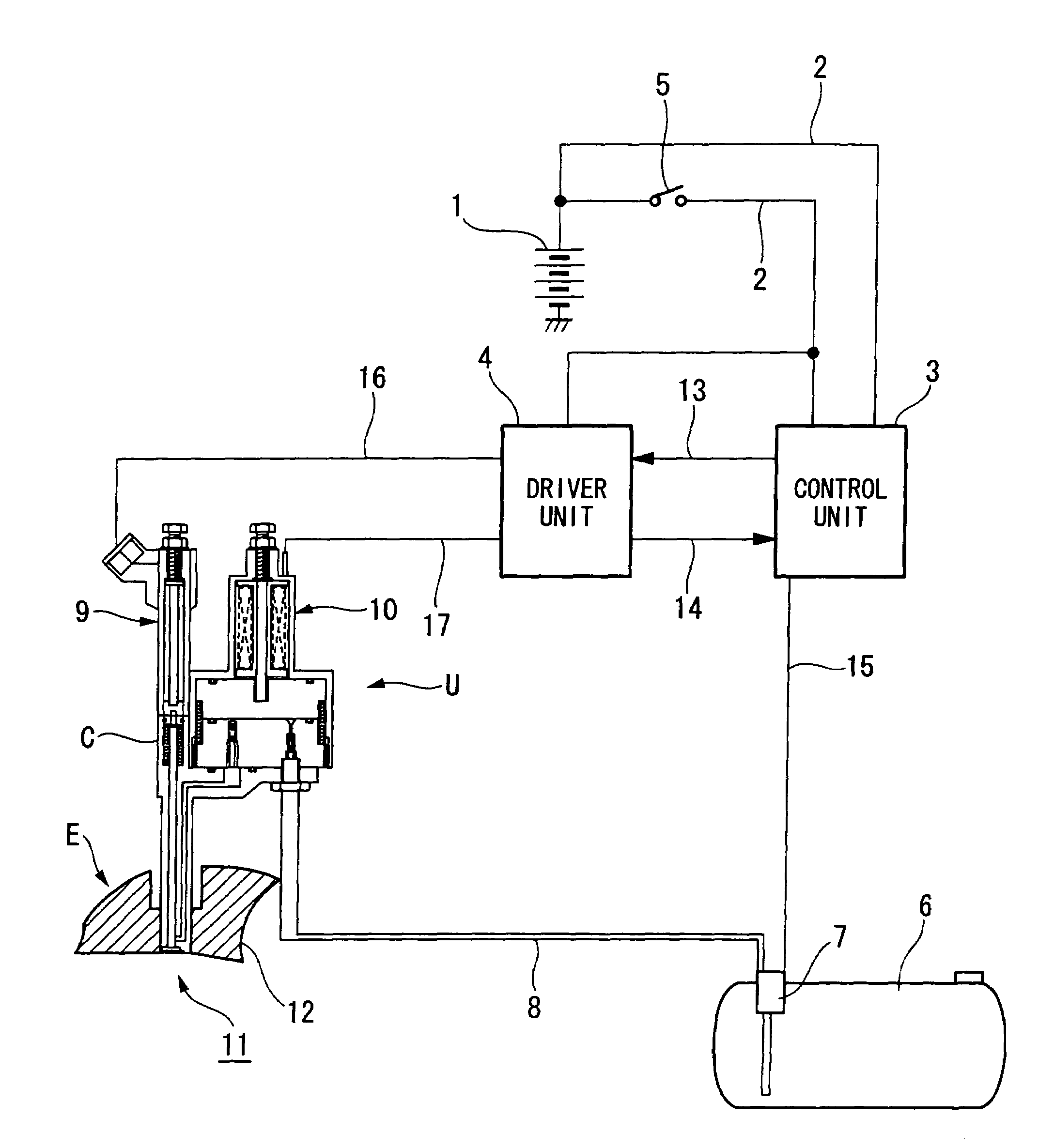
[0030]FIG. 1 shows the system structure of the present invention. The reference numeral 1 denotes a 12V battery, and a control unit 3 and a driver unit (a driver unit) 4 are connected to this battery (BATT) 1 via power supply lines 2 and 2. One of the power supply lines 2 has an ignition switch (IG) 5. One of the power supply lines 2 is branched off at the downstream side of the ignition switch 5, and is connected to the driver unit 4.
[0031]The reference numeral 6 denotes a fuel tank, and a low pressure pump 7 of the fuel tank 6 is connected to a fuel injection unit U via a low pressure fuel pipe 8. This fuel injection unit U is one which includes, unitarily within a casing C, an injector 9 (a fuel injection valve) of a piezo element (piezoelectric element) type, and a high pressure fuel pump 10 (a fuel pump) of a magnetostrictive element type. The fuel injection unit U is fixed in the cylinder head 12 ...
second embodiment
[0073]Next, a fuel injection unit U which utilizes a solenoid type injector, which is the present invention, will be explained based upon FIG. 7.
[0074]It should be understood that since, apart from the solenoid type injector, the other structures and operation are the same as for the previously described first embodiment, in FIG. 7 the same reference symbols are affixed to the same parts, and explanation thereof will be curtailed.
[0075]As shown in FIG. 7, in the housing portion 9a of the injector 9, at the location where the discharge end of the high pressure fuel passage 18 opens, there is provided a needle 70 (an opening and closing valve). This needle 70 is provided so as to be freely slidable via a spring 60. The upper portion of the spring 60 is fitted into a concave portion 63 which is formed by a circular cylinder shaped fixed core 61 and a inner collar 62 which is pressed from upward into its interior. This inner collar 62 is arranged to press against the upper surface of th...
third embodiment
[0087]Next, a third embodiment will be explained based upon FIG. 8.
[0088]In the embodiments, the driver unit 4 was only shown as a structural element, and its concrete arrangement and positioning were not explained; but, in this embodiment, the driver unit 4 (for convenience, shown in the figure by hatching) is arranged so as to surround the magnetostrictive element 27.
[0089]Instead of the harness 39 and the coupler 40 for electrical supply which were extended from the coil described in the explanation of FIG. 2, a harness 58 is provided to the driver unit 4, for connecting the driver unit 4 and the control unit 3.
[0090]It should be understood that, since the other structures and operation are the same as for the previously described embodiments, the same reference symbols are affixed to the same parts, and explanation thereof will be curtailed.
[0091]Thus, according to this embodiment, by arranging the driver unit 4 around the perimeter of the magnetostrictive element, it is possibl...
PUM
 Abstract
Description
Claims
Application Information